Reverse Engineering with Creaform and SOLIDWORKS
Reverse Engineering with Creaform and SOLIDWORKS
The hand held Creaform 3D scanners are a great addition to your Inspection lab to speed up bottlenecks and get more info quicker on your parts, but they can also be used for quick and effective reverse engineering. Once we have all of this scanned data acquired, we can use the VXElements software to extract all of the useful information we might need to build up a new part or a variation of the existing Geometry.
In this case, we are going to be building a completely new product, but we want it to fit onto an already existing piece of hardware. This situation comes up a lot with companies wanting to, for example, make third party parts and retrofits for cars and trucks. Once we get in and do a quick 5 minute scan of the area where our part will fit, we can build up a model based on that info.
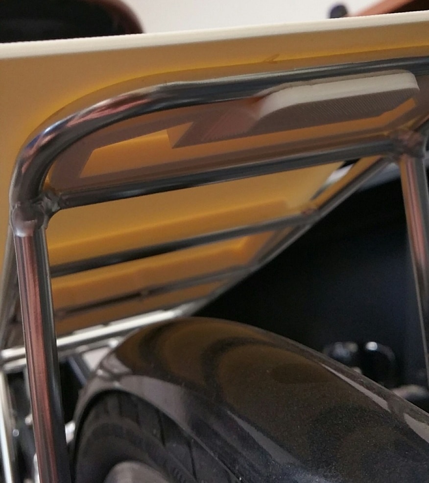
Here we have a bike with a cargo rack on the back of it. I want to make a container that will fit neatly onto this existing rack so I no longer have to just bungee cord a bag onto it.
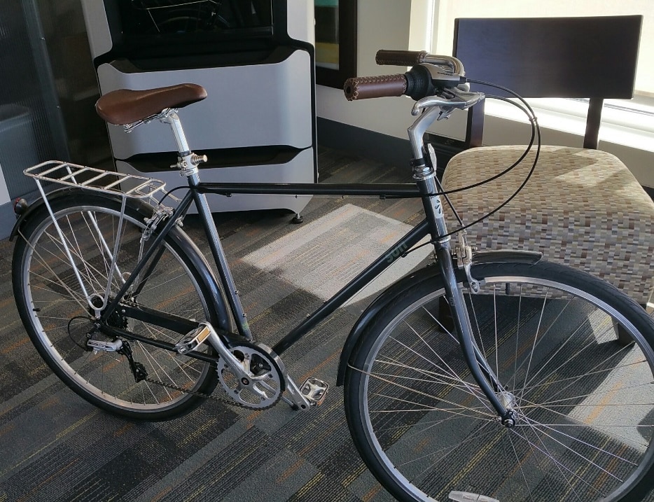
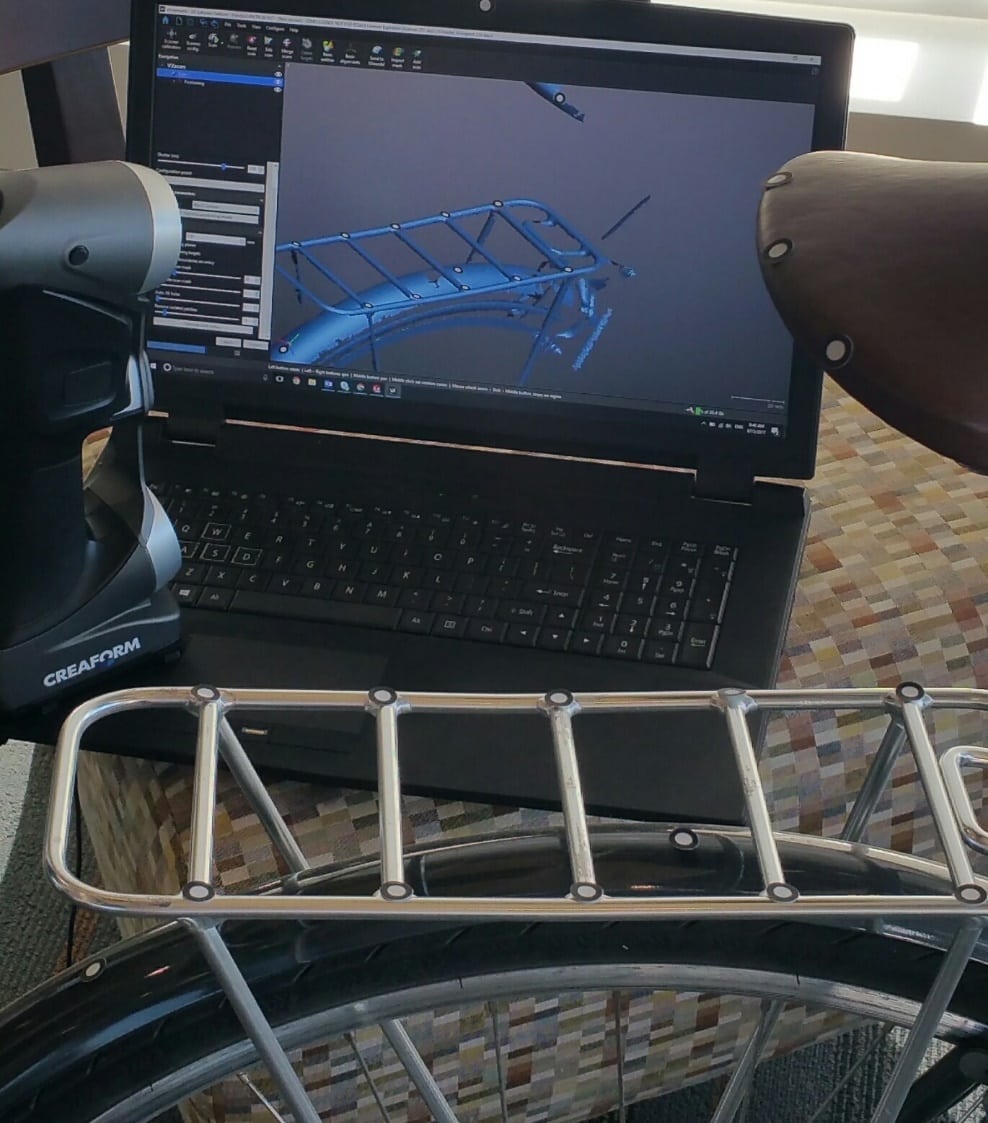
With the Handy Scan 700 that I have on hand and all I have to do it put down a few tacking targets and give it a quick scan to get all the data I will need. Even with this shiny metal part, the Handy Scan 700 can pick up the data without any issues and no need to coat it in an anti-reflecting material. I can even scan the surrounding area, like the back of the bike seat, so I know what kind of head space I have to work with to make the box fit neatly around the contours.
Once I have the scanned data acquired, I can extract the needed data from it. For this, I converted the scan of the rack into a top down silhouette. The rack is a bit used and banged up, so the I don’t have perfectly straight lines.
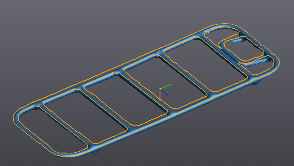
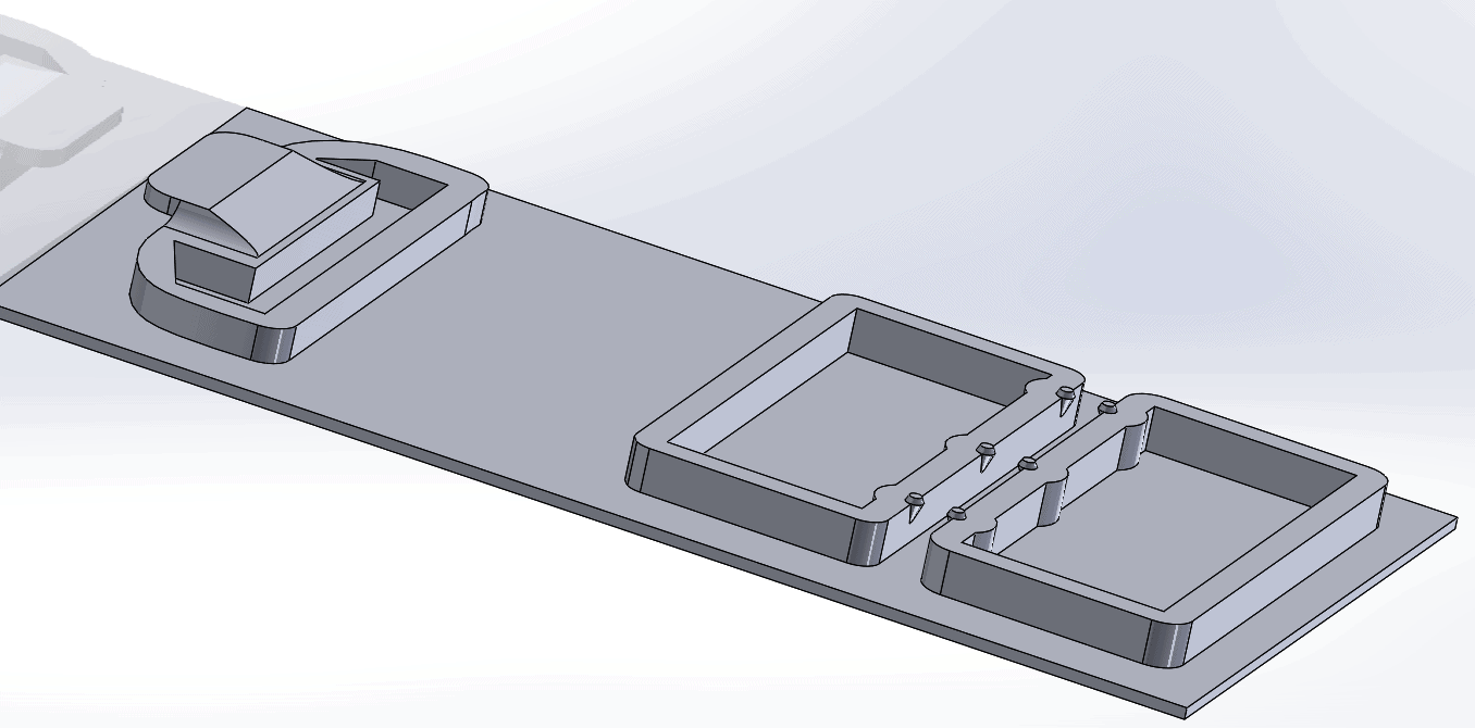
Once we have the silhouette curve I can transfer it directly from VXElements into SOLIDWORKS. It opens in SOLIDWORKS as a part file and the curve comes over in its own sketch on a sketch plane, ready to be used. Now we can either draw our own geometry and use the imported sketch as a guide, or we can use the sketch directly. After a few quick extrudes are generated from the curve, I have this simple part:
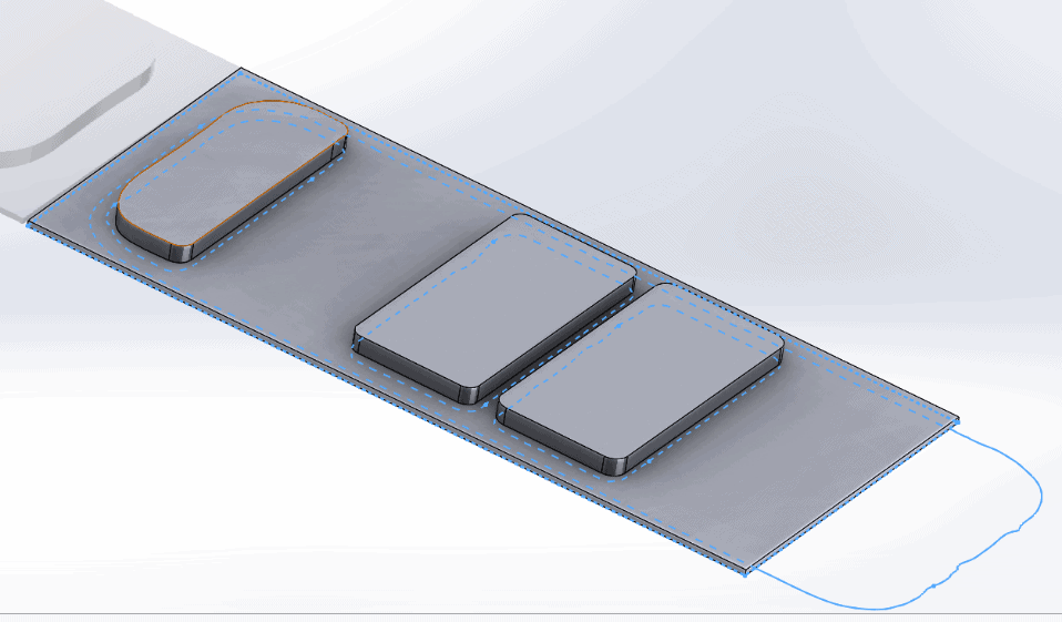
Now we can optimize the volume of the part and also add some more geometry to make it more functional. This part has a lip at one end to fit around the back rail and some snap fit features on the other end to connect to one of the other bars. Now it looks like this:
Now for the test fit. Open the SOLIDWORKS file directly in GrabCAD Print, no need to translate it into an STL file now, and send it to the Stratasys F370 to print in ABS. 3 hours later…
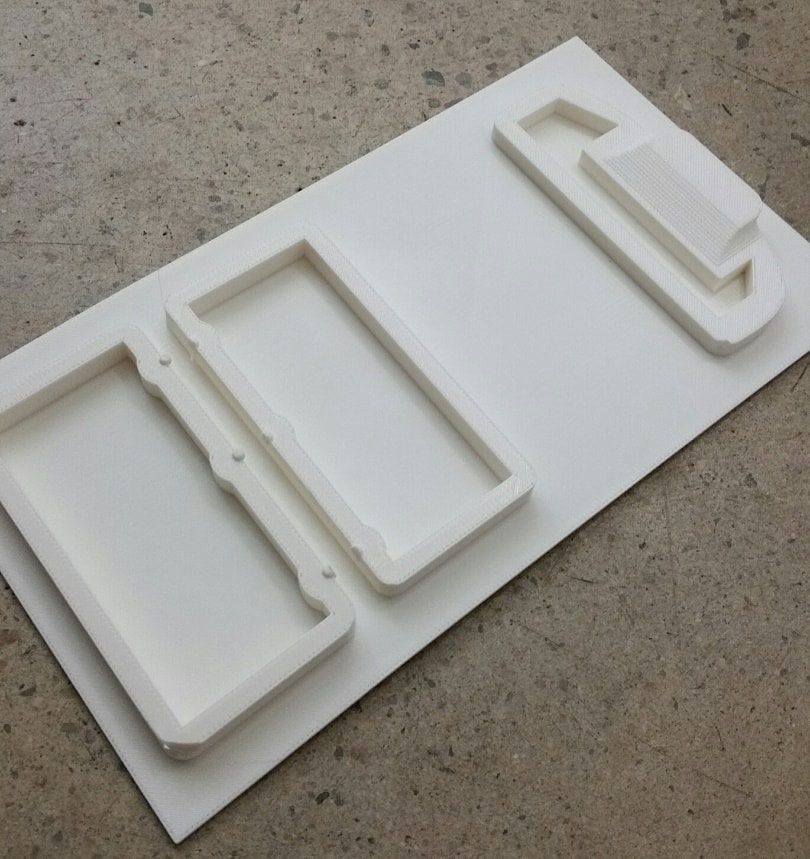
The support material pops right off and it fits on nice and snug on the first try. So long to making multiple iterations just to get the part to fit! Now I can spend my time making the box better/stronger/lighter and not waste time on just getting it to work.
Tim Crennen
Application Engineer
Computer Aided Technology