Polyworks Airfoil Gauges
Airfoils (such as wings, propeller blades, turbine blades, and hydrofoils) are very complex and optimized shapes. Each airfoil design will have a large amount of unique and hard to measure values to it. It’s all well and good to have the design on your CAD data but if you want to evaluate this information on real-life airfoil it can be very difficult and time consuming.
Lucky for us with Polyworks Inspector we can access the ‘Airfoil Gauges’ to automatically extract information from the scan data of an airfoil that we acquired with a Creaform 3D Scanner. Below is an image illustrating a lot of the different measurements that can be quickly extracted using the Polyworks Airfoil Gauges.
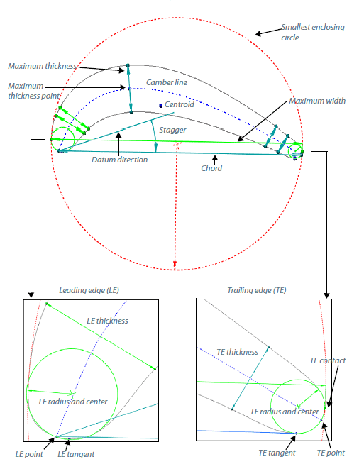
Measurements that can be automatically extracted include:
- Area
- Camber Line
- Leading Edge info
- Trailing Edge info
- SEC Radius
- Max Thickness
- Max Width
- Chord Length
- and more with data to reference geometry deviations
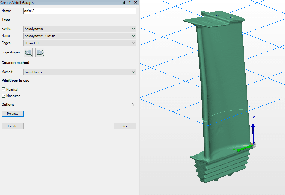
Once we have a good scan of the airfoil we want to inspect, creating the gauges is extremely easy. The first thing we will need to do is create a plane through the cross-section of the airfoil we want. Next, if we have some CAD data to compare it to, or we can just extract the standalone values, we can import the CAD data and perform an automatic alignment of the CAD and Mesh data. Then we just activate the airfoil gauge and it will extract all relevant information automatically.
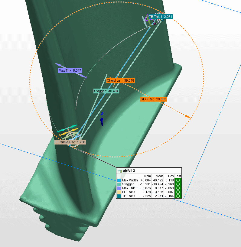
This is a very powerful tool that can really empower you to save time and increase the accuracy of your measurements. This combined with the customizable reporting options within Polyworks results in easy to understand and convey information that adheres to your specific company standards.
Tim Crennen
Sr. Applications Engineer – 3D Printing/ 3D Scanning/ Solidworks
Computer Aided Technology, LLC