3D Scanner Basics: Reverse Engineering and Inspection
Welcome to Part Two of a short series of posts about the basics of 3D scanners. Part One talks about what 3D scanners are and how they work.
What are they used for?
Maybe the previous article piqued your interest or maybe you already knew about 3D scanners but weren’t sure how they would be used in your operation. This article will go through the two main uses of 3D scanners and compare them to other common technologies in these uses. While 3D scanners have many applications, the two main uses for industrial design and manufacturing are reverse engineering and inspection.
Reverse Engineering
Reverse engineering is where you take an existing part and then use it as a reference to create a model in a 3D CAD software such as SOLIDWORKS.
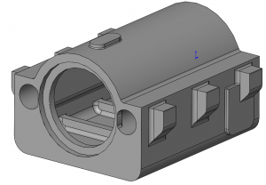
This can be very useful when manufacturing drawings are missing, part files are lost, or legacy drawings don’t exist in digital forms. Alternatively, it could be used to help the design process where an industrial designer shapes the form of a product in clay and the shapes need to be transferred into CAD software. This process can be done in multiple degrees of detail ranging from just creating a “dumb solid” in the CAD software that acts mostly as a reference to creating a fully parametric and editable solid by building the part from scratch in your CAD software.
Traditionally, measurements would be taken with physical tools and gauges such as rulers, calipers, and radius gauges in order to gather information about the part’s features. Using these tools takes a high degree of skill to be accurate and repeatable and can be a very lengthy process. Additionally, with curved, organic surfaces, creating an accurate representation in a CAD program would be nearly impossible.
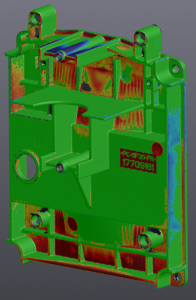
The process of reverse engineering can be immensely sped up and improved with 3D scanners. In a matter of minutes, millions of measurements can be made to create a mesh in real-time. This mesh can then be turned into a surface ready to import into CAD. Reference entities such as planes, cylinders, and cross-section profiles can be created from the mesh geometry and transferred to help you create a fully parametric solid model.
If you want to know more about reverse engineering, our scanner guru Bob Renella recently wrote a great blog on the subject that can be found here.
Inspection
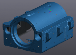
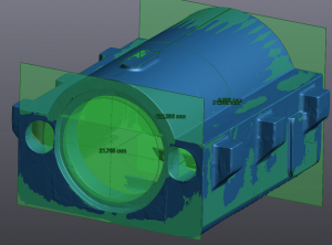
Inspection, on the other hand, is comparing a real-world object with a pre-existing 3D model.
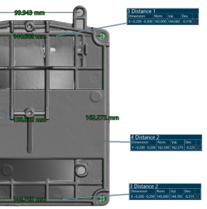
This can be extremely beneficial for several applications, particularly quality control. The VXinspect portion of the VXelements software can take IGS and STEP files and identify different faces and features that can then be compared to the mesh data from your scan. This can not only give you information such as comparing surface profiles and feature locations but can also give you GD&T (Geometric Dimensioning and Tolerancing) call-outs like true position, flatness, or circularity.
Again, 3D scanners can greatly increase the speed, accuracy, and/or ease of the inspection process over existing methods. Of course, compared to hand tools the scanners are much faster, more accurate, and scanned data can also be directly compared to a CAD model nearly instantly. The other main technology used to inspect parts is a coordinate measuring machine (CMM) which use a programmed probe to measure the surface of the parts. While these can be more accurate, they also come with several drawbacks. Most notably, the speed and the sheer number of measurements taken is much better with 3D scanners as well as their flexibility. Where the CMM has a maximum volume and a fixed setup requiring a climate-controlled lab, 3D scanners are shop-floor ready and can measure almost any size parts.
Conclusion
These are just the most common uses we see for 3D scanners, however they can be used for plenty of different purposes giving different end products. It is extremely common for people that visit us at our events or trade shows and see this technology in action to very rapidly think of several uses that would improve their manufacturing and design processes. If you are unsure if this technology would fit your needs, get in contact with one of our salespeople who can start a conversation with you and our team of Application Engineers who will help you find the correct product and processes for you.
Nathan Fears
Application Engineer – 3D Scanners & SOLIDWORKS
Computer Aided Technology, LLC