Tips for Using Manual Surfacing Tools in Creaform's VxModel
The manual surfacing tool in Creaform’s VxModel software is a very powerful tool when reverse engineering complex surface parts. However, this power can be a challenge to tame. To help you take advantage of this powerful tool I have created this short guide.
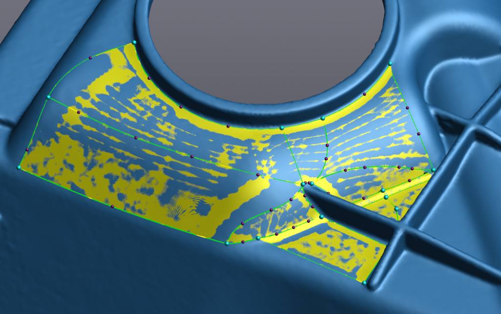
The main concept behind using this tool is creating 4 sided shapes covering any area of interest on your part. To start creating the shape, left click on the scan and proceed to add intermediate points with a single click and corners with a double click. After drawing a curve the tool can be deactivated with your Esc key. These shapes need to include only four curves and four corner points as shown below.
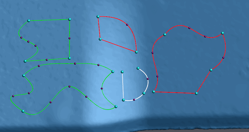
These shapes do not need to resemble squares and they may have as many intermediate points as you need. The intermediate points exist to help you contour the curves to select the area of the scan you wish. When an area is good, the curves will turn green. Incomplete areas display with white curves. Rejected areas display with red. It is possible to add both corners and intermediate points to existing curves. To add a corner point, click on the curve and then start building the curve away from the existing one. For an intermediate curve, click on the curve then trace that curve back to its nearest other point then dismissing the tool with your Esc key. While the tool is deselected you can delete points, curves, or curve segments using the right click menu. Also, while the tool is dismissed you have the ability to move and adjust any of the existing points.
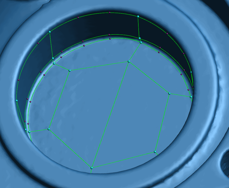
Creating large areas of coverage that encapsulates the entire surface can be tricky. I recommend following the inflection curves and major features in the part can help you to visualize a way to pattern the curves across the scan. A tip I use for capturing circular features is to use a hexagon centered in the circle that I then build a web off of.
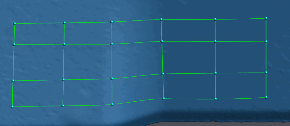
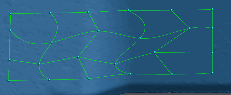
To quickly create a grid across an area, you can draw intersecting curves. This will automatically create corner points at all of the intersections. Both curves will still maintain the curve parameters and tangency at those points when the corners are automatically created. If you do not want the tangency to be preserved across that point, you can manually create a corner at each curve intersection. The effects of this will likely only become visible if any of the points are adjusted after creation. I have illustrated this in the following images.
After creating the surface outline, you can preview the surface that will be generated using the button in tool window on the left. When the computer generates the surface it further divides builds a finer line pattern by dividing each line segment into finer grids as defined by the “Number of Control Patches” option, also in the tool window. Increasing this number will generate a higher resolution surface in a way similar to the mesh size settings in VxScan. This subdivision does not acknowledge intermediate points. So, the division will still be evenly spread between the corner points.
Once the preview is generated, simply click save and your surface will be ready to export to your preferred CAD software. One final tip. Once you create a manual surface you can still fully edit the surface by double clicking on that surface feature in the entities tree. This includes modification to the curve pattern and changes to the number of control points.
Hope this helps the next time you need to reverse engineer a complex part!
Collin Mancheter
Application Engineer
Computer Aided Technology, Inc.