Accurately Reverse Engineering an Assembly
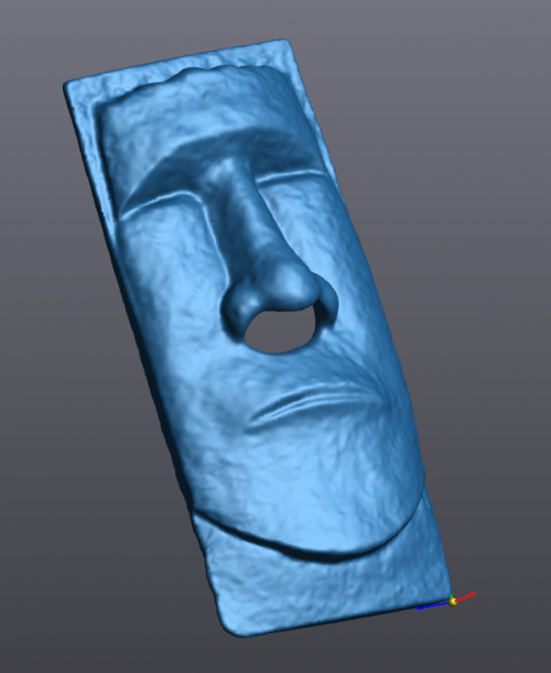
Reverse engineering an assembly accurately at the part level and determining how the parts fit together can be challenging. I ran into a simple example of this while recreating a tissues holder for our office. A coworker of mine has an Easter Island head tissue holder that has been broken.

In this case, the head had come unglued from the base and would not stay upright without falling off. Luckily it could stay together when laying down. We’ll go over the steps needed to reverse engineer both pieces and put them back together accurately in SOLIDWORKS. Scans should be made of the assembly as a whole and also of the important pieces by themselves.
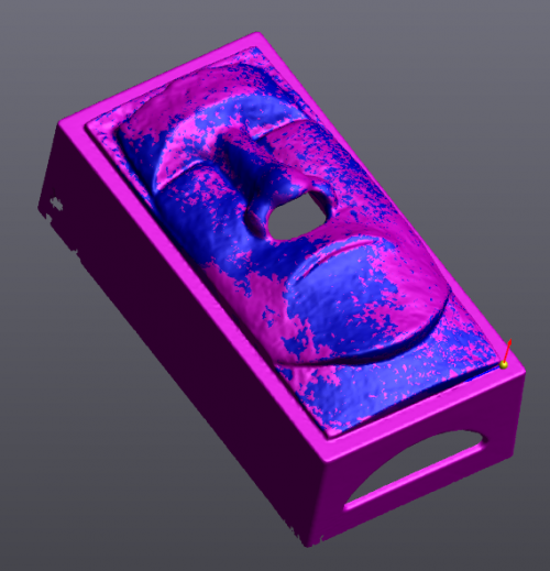
First, take it apart and focus on one part. In this case, the head will be scanned first. To get a complete mesh, I scanned the front, the back, then fastened it in a bench vise grip and scanned the bottom all the way around. This last scan was used to more accurately bridge the first two scans together. After merging the scans together and filling in holes, I could begin!
Now that this mesh is watertight, an Auto-surface will create a full surface that will become a “dumb” solid when transferred to SOLIDWORKS. To make the back completely flat, a plane was created of the back face and transferred as well. I offset the plane a short distance into the head and used it to split the part.
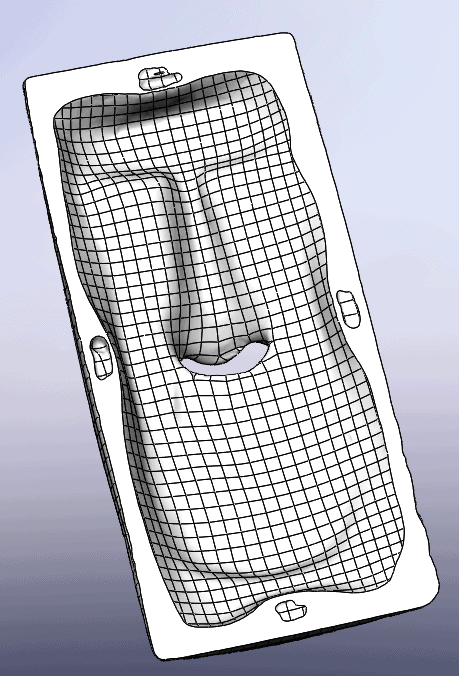
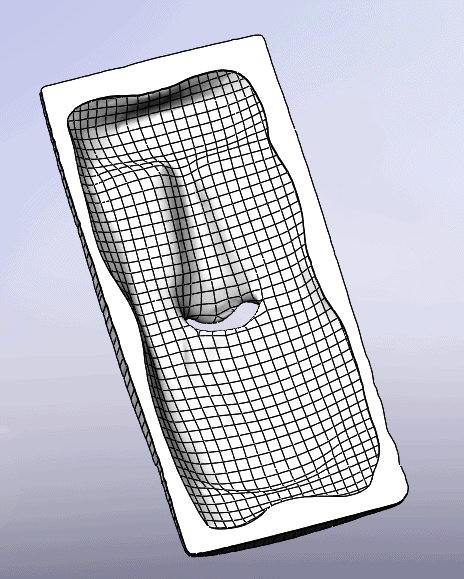
The original design of the part had holes in the back that need to be filled in. This can be done with the Delete Face command, using the Delete and Patch method. The back can then be extended up to fill in what was cut away with the plane.
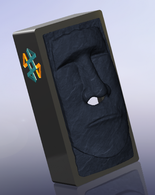
Once this is done, the head can be placed back on the box and scanned together. In some cases, I would want to scan the box separately first and then again with everything put together. In this case, the opening along the interface is very simple and only needs to be big enough to allow a tissue through. Once this is scanned, another issue is created as shown below.
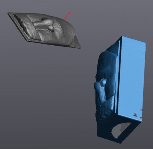
The alignment is obviously off, and the back face which was used as part of the original alignment does not exist in the new scan. To correctly position the new scan, we will use an alignment tool called “Best fit”. This allows the program to create a surface best fit that will place the meshes correctly on top of each other.
Once this is done the entities for the box can be created and transferred to SOLIDWORKS!
For any and all other questions regarding Creaform 3D scanners, contact Computer Aided Technology to get in contact with one of our local 3D scanning experts!
Chad Whitbeck
CATI Reverse Engineering Specialist
Computer Aided Technology, LLC