Application Highlight: Scanning for Thermoforming
In this blog, we’re going to take a closer look at an application that a scan-to-CAD workflow can really improve turnaround time on. Packaging manufacturers are tasked with creating packages that hold, protect, and display various consumer products. Two very common types of packaging include blister packs or clam-shell packaging. Though slightly different in their function, their manufacturing process starts out essentially the same. This where scanning can come in very handy. Both styles begin as thin plastic sheets that are cut to size, heated to the point of pliability, then formed into the necessary geometry via vacuum suction. This process is commonly referred to as thermoforming.
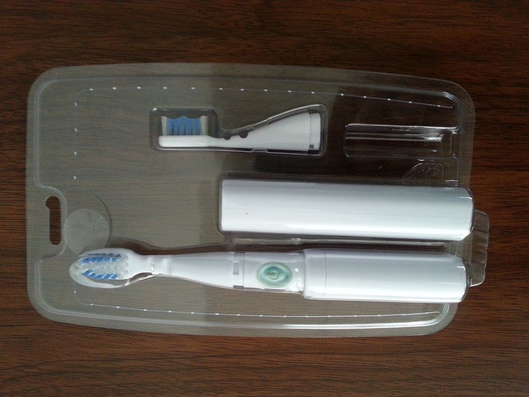
To start the process of thermoforming, manufacturers need to know what their customers need packaged. Ideally for the manufacturer, this means the customer sending the CAD files as well as sample parts to be packaged. From there, they can use the CAD files to design the molds needed to form the plastic sheets and create the packaging. Then they can test the function of the packaging using the sample parts from the customer. There are two common hang-ups that can happen here. First, the customer may not want to send proprietary CAD data, or they might not even have CAD data of their parts. This means a significant amount of time for the manufacturer’s engineers to reverse engineer the product by hand in order to create the design for tooling. Also, even in the best-case scenario where they have both the parts and the CAD files, there is no guarantee that the real-world parts on hand match the CAD well enough to use the CAD data to design tooling. In both scenarios, a CAD file needs to be created to accurately represent the product in order to design tooling. Here is where scanning can help out. By using a Creaform 3D scanner, we can capture the true, real world geometry of the product and turn that into a file we can use to design tooling. Going this route versus the traditional manual method saves countless hours of engineering time and delay. Not to mention the increase in accuracy over reverse engineering by hand measurement. Let’s look at that process in detail.
We will be creating the model for a common electric toothbrush model from Oral-B.
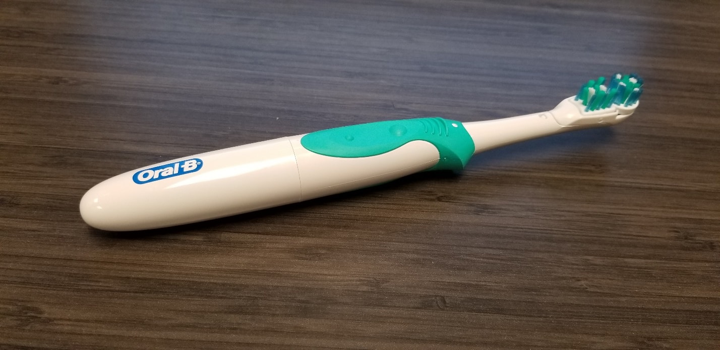
Our first step is to digitize this toothbrush using our scanner, the Handyscan Black Elite. This is a blue laser scanner capable of high accuracy and high-resolution scans, which makes it a perfect fit for our thermoforming tooling application.
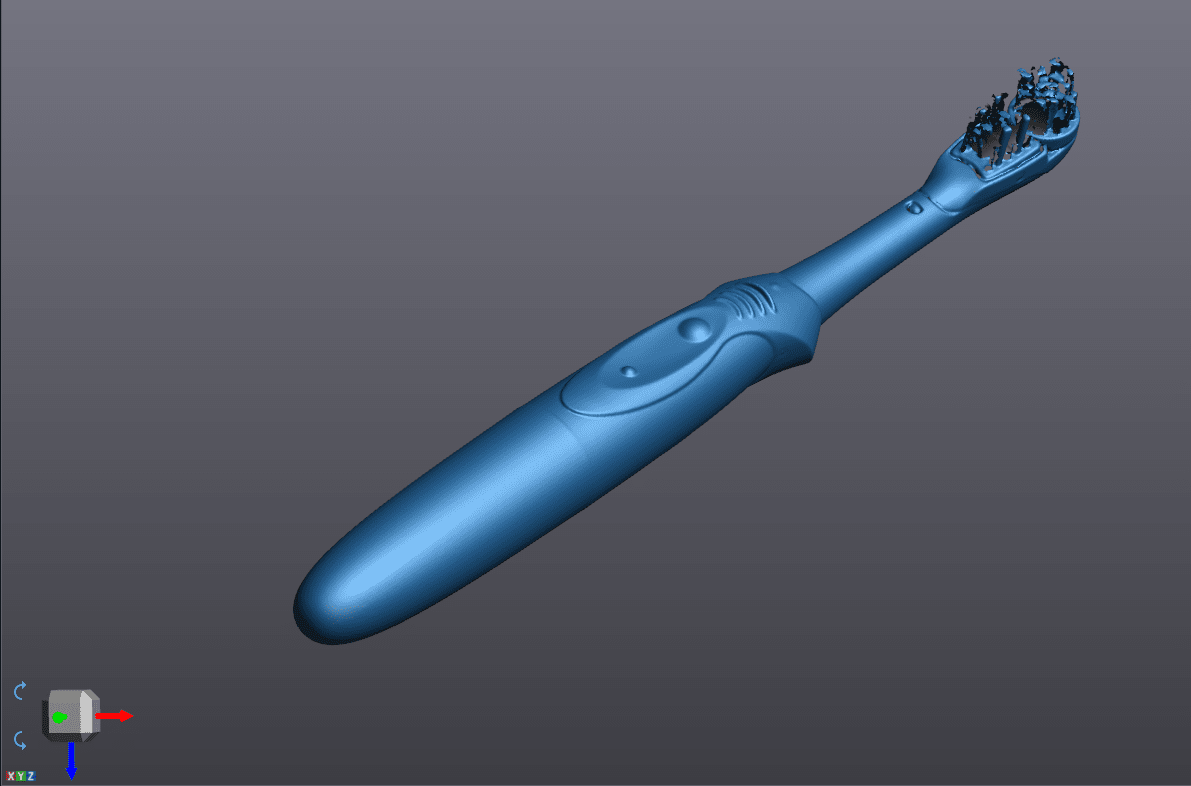
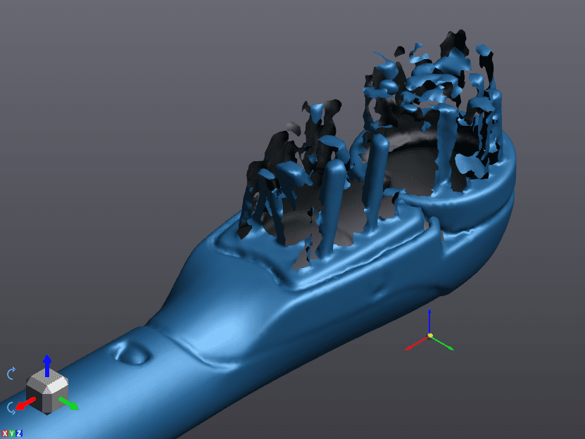
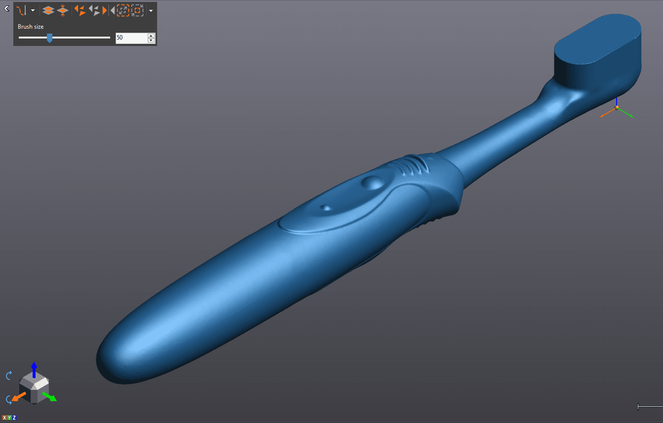
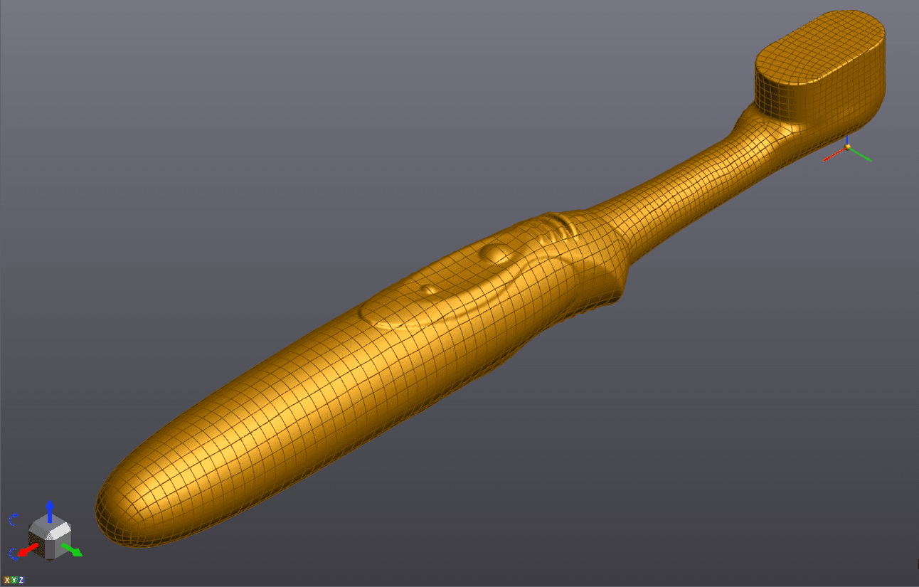
Here is our resulting model after scanning. Due to the very thin geometry of the bristles, we weren’t able to get the best fidelity scan in that area, but you’ll see that that wont negatively affect us at all in our goal to create thermoform tooling.
Now we’ll move over to our reverse engineering software, VXmodel, to do some mesh editing and conversion to CAD.
After some minor mesh cleaning and alignment, we can begin working on the bristles. For the purpose of thermoforming, our goal isn’t to individually wrap each and every bristle on the brush, that would be impossible from a thermoforming perspective. We just need to make sure there is a space large enough for the bristles in the final packaging.
So we’ll start out by fitting a plane across the top most bristles to make sure we clear them in the final design.
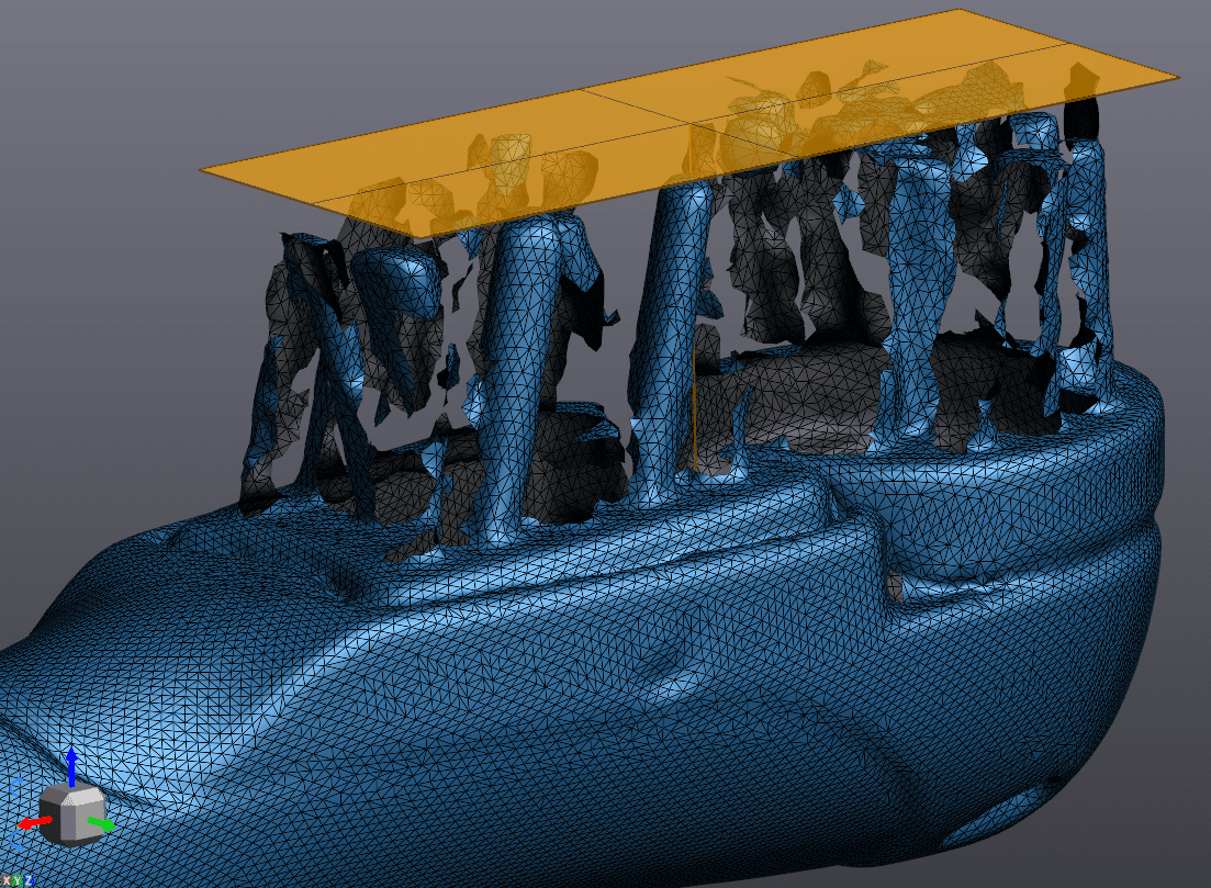
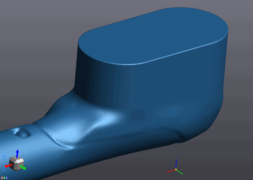
Next we can actually just delete all of the bristles. We don’t need them anymore. We’ll use their footprint to extrude a solid up to the plane we just made.
Now, we could just use this footprint to extrude, but let’s make it look a bit nicer by fitting the triangles to a perfect slot shape.
Extruding that slot shaped boundary, we get the following.
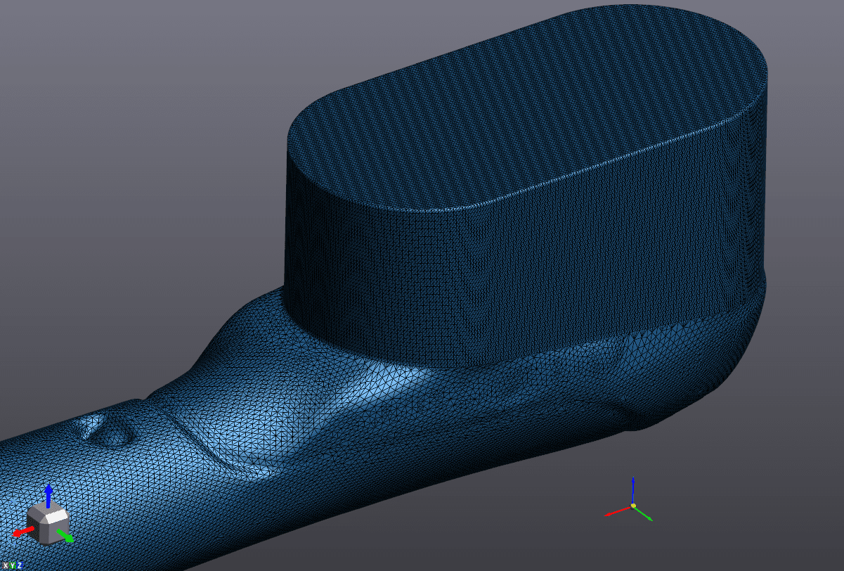
Next, lets use the defeature tool to smooth that sharp transition a bit.
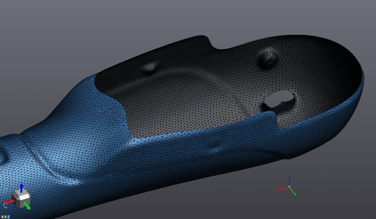
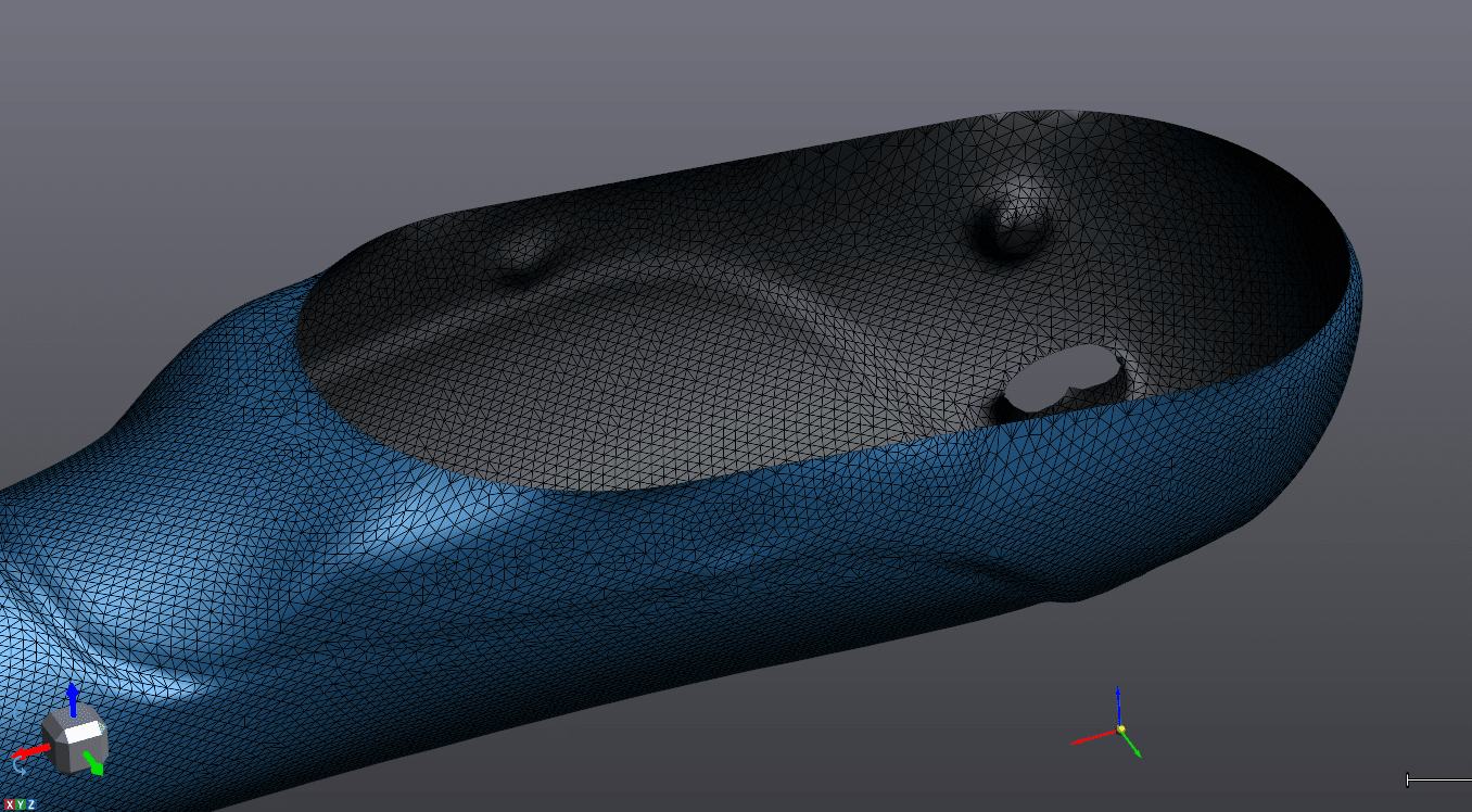
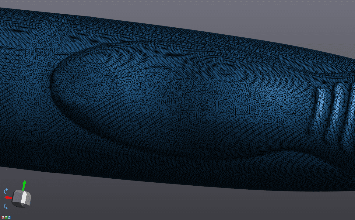
Bristles are now fixed. Now we just have to fill any minor mesh holes and remove any small features we don’t want to consider for our tooling design such as lettering or depressions in the part’s surface. 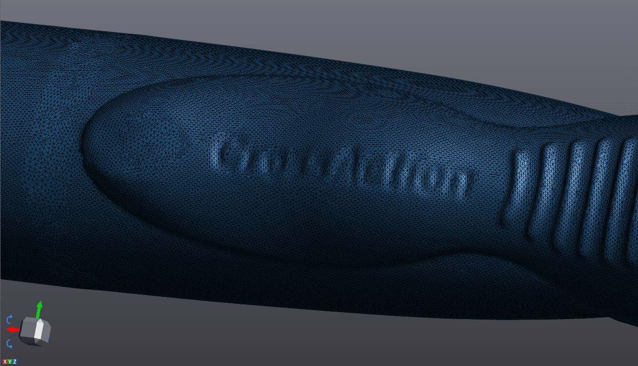
Now we’ll offset our mesh 0.015” to allow some clearance between the packaging and product. Its much easier to do offsets now while we’re still at the mesh stage vs doing it once we’re in CAD form.
Our final step will be to run an auto surfacing function on this new offset mesh. This converts the data from mesh surface to a CAD friendly STEP file that can now be used in Solidworks to design our production thermoforming tooling.
From here, we can use this auto surfaced file to create a 3-cavity pattern for production tooling in Solidworks.
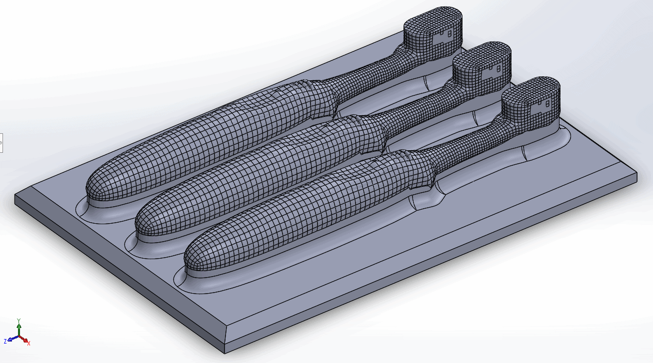
Now that you’ve seen the process end to end, you can see how useful a scanner is to capture the complex and unique curvature of the surface of the toothbrush, a process that would be very difficult or impossible to do accurately with manual measurement methods.