Bonded, Bolted, or Pinned – Why You Should Simplify Your Analysis
Simplify, simplify, simplify! I cannot count how many times I’ve had this discussion with customers when reviewing their CAD models and listening to what they want to analyze with SOLIDWORKS Simulation. I know how easy it is to start a new SOLIDWORKS Simulation study and begin setting up an analysis on fully-featured CAD models – click a button and you’re on your way. Let’s look at an example of starting simple and working towards the complex with SOLIDWORKS Simulation that I hope will illustrate why you should start as simply as possible.
I have a two-part assembly consisting of two identical plates. They are made of 1-gauge (7.145 mm thick) Alloy Steel, are 150 mm long x 60 mm wide, and have a pair of 8 mm holes at one end. The two plates are fastened together with M8 x 1.5 mm Class 8.8 hex head bolts with corresponding nuts.
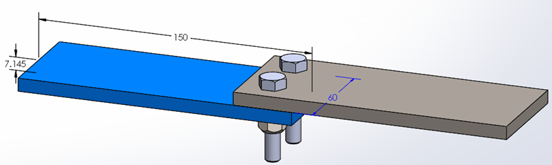
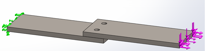
The bottom plate will be fixed on the left side, away from the bolt holes. The top plate will have three equal loads applied to the right side face, one each along the X, Y, and Z axes. For all the SOLIDWORKS Simulation studies, the load magnitude will be set at 250 N for each of the three loads.
My first SOLIDWORKS Simulation study will be very simple – All Bonded. The two sets of fasteners will be excluded from the analysis. Also, where the two plates touch, I will allow a Global Bonded Contact to connect the two plates. This contact condition assumes that the plates are perfectly connected where they are face-to-face coincident and is significantly stiffer than the real-world assembly.
For this initial, greatly simplified version of my two-part assembly I added a mesh control to the bolt hole faces, 1.5 mm in size, and used a global mesh setting of 3.5 mm using the Standard meshing algorithm. This All Bonded study solved in 8 seconds.
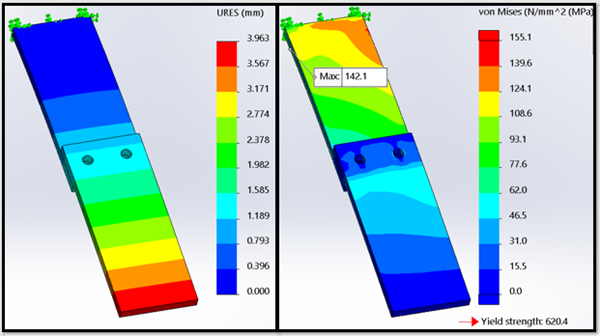
Reviewing the results of this All Bonded analysis indicates the maximum resultant displacement is 3.963 mm and has a maximum stress of 142.1 MPa. The displacement result is significant in that this ultra-stiff version of my assembly indicates the least possible displacement the real assembly might experience. The maximum stress value isn’t as important, though the location is. At least for comparison purposes with the studies to follow. Since the stiffest region of the model is around the bolt holes, the maximum stress will be calculated away from the real bolted connection. (Note that I set the maximum value of the stress plot to be 155.1 MPa, one-fourth the yield stress value for the material. This will be consistent as I review the later study results.)
The second analysis I will set up is a locally bonded version. The bottom edge of both holes on one of the plates will be bonded to the adjacent face of the opposite plate. The two plates will have a local No Penetration contact added to the analysis. This slightly more complex analysis achieves two things – a more realistic interaction between the plates and a less stiff interaction around the two bolt holes.
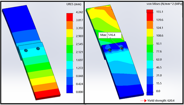
This analysis took 203 seconds to solve, a 25.4x increase in solution time! The maximum resultant displacement is 4.242 mm. This is significant because this “soft” version of the analysis indicates the maximum displacement that I could expect from the real assembly. The maximum stress is significantly higher, 516.4 MPa, though the highest stress location is now at the local bonded contact edge of the bolt holes. Both the increase in stress and change in stress location were expected.
The next analysis maintains the No Penetration contact between the steel plates but replaces the local bonded contact with pin connectors. Each pin was set up as Alloy Steel for the material, the same as the steel plates. I also used the Pin connector options to prevent both axial rotation and translation of the pin connector. With this SOLIDWORKS Simulation study, I’m finally introducing a connector to represent the actual M8 bolts in the analysis, though the Pin connector is still a simplification of the bolted connection.
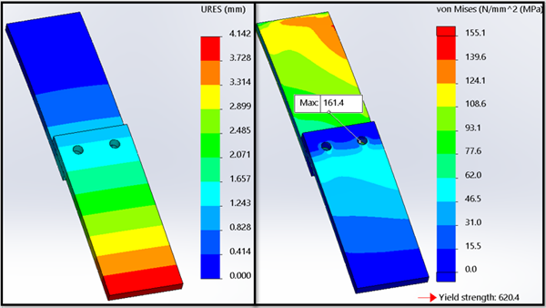
The Pinned version of my Finite Element Analysis study solved in 90 seconds, or 11.3x longer than the original All Bonded study. The maximum resultant displacement is 4.142 mm, which is 0.1 mm less than the resultant displacement results of the Local Bonded study. The highest stress calculated is now 161.4 MPa and, like the Local Bonded study, is again near the bolt holes, as expected.
The last version of my assembly includes virtual Bolt connectors. Like the pinned version, I will use Alloy Steel in the material definition for the bolts. With a bolted connection, however, there is one additional input that is critical to the success of a bolted joint – preload! Searching for recommended bolt preload values of an M8 x1.5 hex head bolt, I found multiple torque values ranging from 17 N.m to 30 N.m. I chose 30 N.m for my analysis. Why did I choose a higher pre-load value? There are several reasons. Higher bolt pre-loads decrease the likelihood of joint separation. If the connection must withstand shear forces, higher pre-load values will increase the friction force resisting relative motion between connected bodies. Finally, higher pre-loads provide the maximum protection against overload conditions while preventing thread loosening which would lead to joint separation.
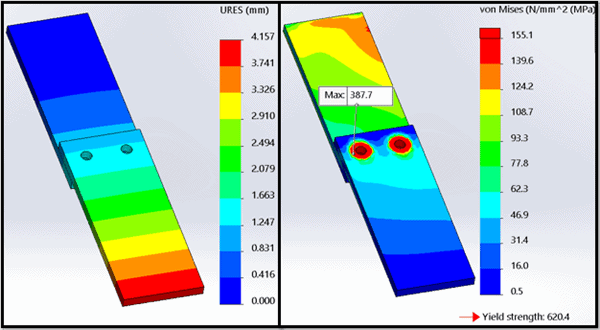
The maximum resultant displacement for the Bolted analysis is 4.157 mm, or less than 0.1 mm different than the Local Bonded study previously solved. The maximum stress result is 387.7 MPa and is located at the two bolts. This is expected as the bolt pre-load compresses the material between the bolt head and nut, leading to higher stress in the bolted joint. This analysis solved in 200 seconds, or 25x longer than the initial All Bonded study.
While this full assembly is not difficult to solve with SOLIDWORKS Simulation, I hope you have started to realize the benefits of simplification. The maximum resultant displacement between the four studies varied from 3.963 mm to 4.242 mm, a difference of 0.279 mm. For many applications, this difference is negligible. The magnitude of stress results did vary significantly, but in each case, it is understood why that occurred. Aside from the magnitude differences, if you compare the stress distribution in the two plates between all four studies, they are nearly identical. The most significant reason to simplify, if you have not guessed by now, is solution time. The All Bonded study solved in 8 seconds compared to 203, 90, and 200 seconds for the more complex analyses. Just think of how many more design iterations you can investigate with that disparity in solution time! When I’m working in development mode, I’ll work on as simple a Finite Element Model I can for speed of the solution. Once I’ve used that information to make informed decisions for design changes, I’ll work on the more complex, realistic Finite Element Models that better represent the actual assembly. I highly recommend you adopt this practice, too. Now go make your products better with SOLIDWORKS Simulation!

Bill Reuss
Product Specialist, Simulation
Computer Aided Technology, LLC