Model Aircraft Control Surface Spacing and SOLIDWORKS Flow Simulation
June 2011 AMA (Academy of Model Aeronautics) Model Aviation magazine had an interesting article Titled “Two of the Big Five model misadjustments” written by Dean Pappas. The two misadjustments were Hinge Gap, and Lateral Balance.
The article caught my attention specifically due to the “flow” diagrams drawn in the article explaining airflow over the wing section and aileron control surface. In the below diagram, taken from the article, Dean explains three cases of air flow relative to a control surface.
- Clean airflow at the neutral control surface desired for level flight.
- When up or down direction is applied to the control surface the air opposite the control surface direction of travel redirects the flow to reattach. This case shows a tight fit between control surface and main structure.
- Hinge gaps allow high-pressure air to leak from one side to the other. This weakens airflow on top of control surface partially destroying the bottom airflows ability to rejoin it. The result is poor control surface response during slow speeds.
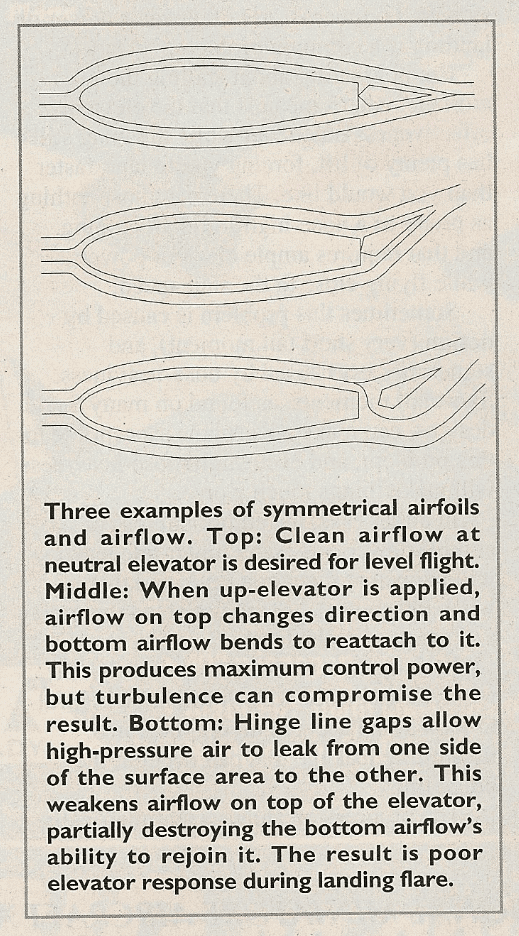
According to the article “The high pressure on top, as shown would leak through, given a chance. That chance would be a gap in the elevator and control surface. The result is a flat sheet of air that squirts through the gap and distorts the outside of the hinge line. This reduces the effectiveness of the elevator and creates extra drag.”
This section piqued my interest as the hinge gap shown is very large, probably for demonstration purposes. Being an avid RC aircraft modeler I suspected that the small gaps I have in my personal aircraft’s control surfaces may not cause this affect. My hypothesis is that a very large unrealistic gap will cause this affect however using standard hinge techniques this affect will not be as dramatic as the article states. According to the article large hinge gaps can be sealed with strips of MonoKote covering resolving the problem. MonoKote is a heat shrink Mylar covering that is a standard in RC Aircraft construction.
This blogs purpose is to investigate the hinge gap spacing required to cause an airflow disturbance and air leak through the gap area.
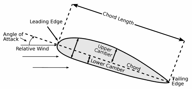
Before we get into the model specifics let’s talk a little about aircraft wing terminology. Below is a diagram explaining common wing dimensions and terminology. The chord length is the distance from the leading edge of the wing or elevator to the trailing edge. The model used in this Flow Analysis is a 5.5″ main wing chord. 0.5″ of the chord is the control surface . The airfoil is symmetrical so the upper and lower camber are equal. The model consists of an extruded wing section with one hinge placed in the middle of the wing.
Three hinge types are standard in the RC modeling community. All hinges are typically spaced evenly across the control surface.
- Standard plastic barrel hinge comprised of two halves held together with a pin. The hinge is typically screwed or glued into place with the barrel tight against both mating sections. Hinges are typically 0.25″-0.5″ wide by 0.5-1″ total length. The barrel typically ranges from 0.0625″-0.125″ in diameter.
- CA hinges are flat woven wicking material that is inserted into a slot cut in the components. No or little gap is present with this style hinge. CA or Cyanoacrylate glue is used to wick through the hinge and bond with the hinged components.
- MonoKote hinges are seldom used in modeling except for small aircraft. The MonoKote hinge is typically a strip of MonoKote that is applied to the top and bottom of the hinge area.
SOLIDWORKS Flow simulation was used to investigate the control surface configurations of four models.
- A base line neutral control surface position using a no gap CA hinge Type.
- Upward deflected control surface using a no gap CA hinge type.
- Upward deflected control surface using a Standard plastic hinge with an 0.0625″ barrel diameter.
- Upward deflected control surface using a CA Hinge and gap of 0.25″
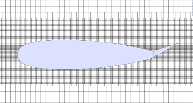
All configurations have a 10 ft/second flow rate and a 0 degree angle of attack. The flow analysis was an external flow problem. A localized mesh control was used for each run to capture refined accurate results across the model boundary. All other default conditions were used for the flow setup.
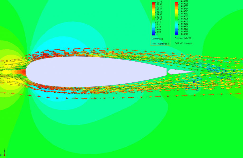
Note All plots show a Pressure cut plot and Velocity Flow Trajectories.
Results:
- The base line model showed a symmetrical pressure on either side of the wing at 14.6 psi and a hinge crossing velocity of 16.45 ft/sec. This is expected results for the area section, hinge, and aileron placement.
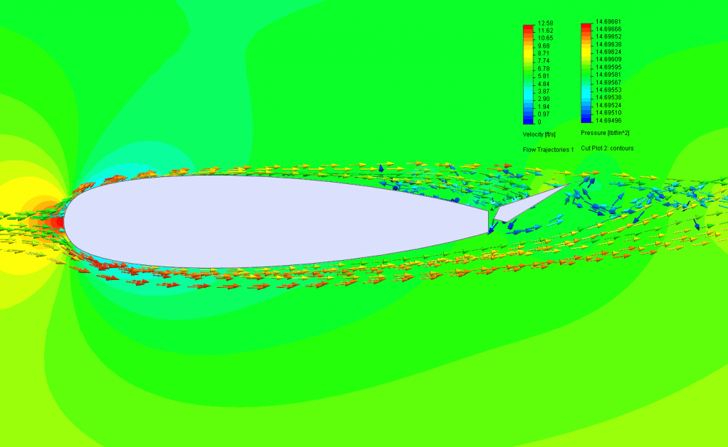
- Flow Run Two shows a higher pressure on top of the aileron of 14.696 psi and a lower pressure on the bottom of 14.694 psi. The flow velocity across the top of the control surface drops to 5.9 ft/sec while the bottom speeds up to 11.2 ft/sec. As the article states the air “bends” to re attach to the flow at the trailing edge. This results in a turbulence on the bottom of the control surface aiding in the force of the air on the top of the control surface to push the trailing edge down.
https://www.youtube.com/watch?v=ZPYYytmfy2E&modestbranding=1
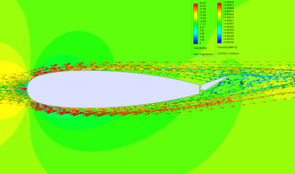
- Flow Run Three demonstrates the 0.0625″ barrel hinge gap and the resulting air flow. The run does show airflow across the gap boundary, however probing the area the velocity in this gap is zero. The flow does extend past the wing trailing edge longer than the non-gap position, however the flow does fully rejoin. The same recirculation under the control surface is seen . The pressure on the end of control surface is however higher at 14.699 psi and lower on the bottom at 14.692 psi. The results show negligible flow through the gap and under most circumstances(slow flight) should not cause loss of control due to bleed through.
https://www.youtube.com/watch?v=_m26EfESLNE
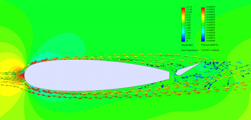
- Run Four had the largest gap similar to the gap in the article’s diagram. The flow results show airflow across the gap boundary and a velocity of the airflow in the gap of 3 ft/sec. The flow does extend past the wing trailing edge longer than the non-gap position and does not rejoin. The recirculation does cause a pressure equalization under and over the control surface. Loss of control surface effectiveness would occur in this scenario.
Conclusions: The article is correct to a point. The gap shown in his diagram would cause a control surface loss of effectiveness, however the gap is way too large to be considered realistic. Most experienced modelers know common practice is to get as tight of a fit between control surface and structure be it a wing, elevator, or rudder. A large gap is not only detrimental but is also unsightly and most modelers avoid them for the aesthetic reasons alone. If a modeler sticks to the new CA hinge or follows correct installation practice for a plastic hinge they will be alright in their flying endeavors.