SOLIDWORKS Electrical Series, #2 - Symbols
In last week's blog, we briefly looked at several schematic tools available in SOLIDWORKS Electrical. This week I would like to look at symbols and their use in the SOLIDWORKS Electrical application. The comprehensive electrical symbol library is used differently from the single line tool when creating 2D schematic diagram. For these diagrams it utilizes the traditional electrical symbols. These electrical symbols are handled much the same way as other electrical schematic capture tools giving SOLIDWORKS Electrical 2D schematic design tool a more traditional look and feel that users are expecting.

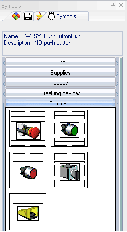
 The symbols are classified into categories such as Connectors, Contactors, Fuses, Buttons, Relays, Sensors, Circuit Breakers etc. These symbols can be used out of the box or customized fairly easily. These customizations can be done to tailor the software to your needs and improve your productivity.
When inserting a symbol, there are several paths to place them on diagram. You can search out for the symbol, or select the category labels to expand out the selections.
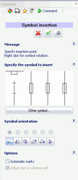
sily since all the parts are organized by location and shown in the dialog windows. Cross-references and the manufacturing information are automatically updated. An important, but quickly overlooked function of the 2D diagram is that when inserted over drawing wires, the wires (lines) are intelligently split into individual segment when inserting a component.
To find your more commonly used symbols quickly you can also leverage the convenient palette tools and browse the different pages quickly to find the symbol needed. Searching for symbols is a simple matter of entering in the string of characters for the desired symbol and the tool will search for everything in the symbol library that matches the entry.
Another function of SOLIDWORKS Electrical is that users can associate it with the manufacturer part data if desired. This association can be completed either manually by create a new component or search for one and benefit from the extensive database (approximately ½ million) of manufacturer parts updated frequently and directly available, as well, within the software.

The circuits of the motor are listed in the dialog box. The RED connection points indicate that the motor is currently disconnected. Green highlighted terminals are indicating the physical connections on the manufactures parts match the schematic symbol. These checks and the schematic association is done automatically.
As you can see, symbols in SOLIDWORKS Electrical give the user another powerful tool in creating documentation of their designs. Next week I will give a look at data reuse and how to create a palette of schematics like the symbols.
Corey Kubichka | Electrical Product Manager