How to Handle Symmetry Fixtures on Shell Elements in SOLIDWORKS
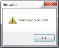
If you have ever used symmetry on a surface body or solid body on which shell elements are defined, you would have had to use a special technique using an advanced fixture. The Symmetry Fixture would not work, as it required you to select a face for the symmetry definition. If you had tried to apply a Symmetry restraint on the cut face of a component defined with shells, you would have received the following warning message.
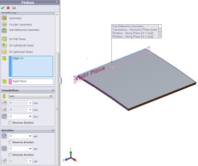
Therefore, in order to apply symmetry to components defined with Shell elements, you would have needed to use the Use Reference Geometry fixture as seen below. And depending on your reference, you would have to be very careful with which buttons you selected for Translation and Rotation.
Well, today I’m here to tell you that this limitation of the Symmetry Fixture no longer exists. We no longer need to select a cut face for defining symmetry. We can NOW select a symmetry ‘edge,’ so anything defined with shells can now use the Symmetry fixture.
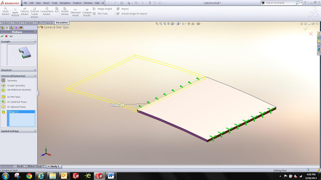
Below, you will see a thin plate defined with Shell elements. And as you can see, I’m using the Symmetry fixture, choosing the ‘edge’ of the plate. Hitting the green check mark, the symmetry fixture is defined. So now, we have a faster and easier way to apply symmetry on components defined with shells.
For more training and tutorials on the many 3D CAD Modeling solutions in the SolidWorks family of products and add-ons, register for an upcoming Event or look into our SOLIDWORKS training.