SOLIDWORKS PLASTICS TECH TIP: Counter Deformed Geometry Export to Counteract Warpage
The primary goals of any plastics part designer and molder are to manage costs and hit critical tolerances. SolidWorks Plastics can help us predict part warpage and therefore optimize our design and process to minimize its occurrence.
There are many factors that affect part warpage. Here are just a handful:
– Part Geometry
– Material
– Fill time
– Cool Time
– Pack Time
– Ambient Temperature
– Gate Locations
When we have done everything in our control to minimize warpage, we still may have to massage our geometry a bit to get the desired net part shape. SolidWorks Plastics can help you make these slight adjustments using the export counter deformed option to use as a template to make cavity design adjustments.
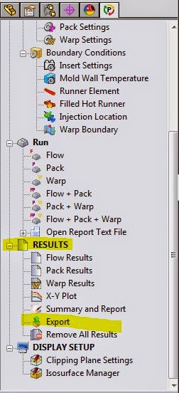
1. Run a fill, pack warp study
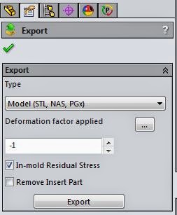
2. Export the STL from plastics; use a value of “-1” to create a counter deformed part.
3. Create a new configuration in your part to keep the geometric “tweaks.”
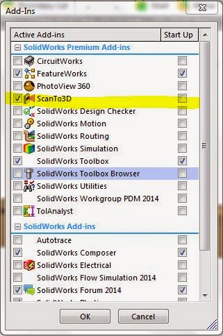
4. Turn on the ScanTo3D add-in for mesh import.
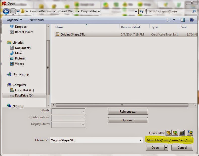
5. To overlay the STL on your part, go to File > Open > Mesh choose the import to same part option.
NOTE: ScanTo3D has options for moving, cleaning up, and creating surfaces from the STL if needed.
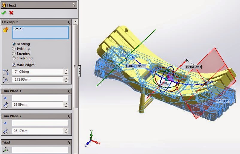
6. Use the mesh as a template to make subtle changes using features such as “Flex,” “Scale,” and “Deform” to match the geometry to the STL.
Now you can copy the plastics study to the modified part and re-run to see how close we came to negating the warpage effects.
You can also take a look at this video where I walk through the process:
For more training and tutorials on the many 3D CAD Modeling solutions in the SolidWorks family of products and add-ons, register for an upcoming Event or look into our SOLIDWORKS training.