SOLIDWORKS TECH TIP: Accounting for Coatings and Determining Pre-plate Dimensions
For certain precision machining operations, the application of coatings will necessitate machining to a slightly different dimension than the one on the final print. While there is no direct feature in SOLIDWORKS to just remove the coating thickness, this type of operation can be completed in about three steps using a few of the lesser-known SOLIDWORKS features.
The basic idea is to create a model of the coating thickness and subtract it from the completed part. It’s actually simpler than it sounds.
To start the process, we will make a copy of the body. To be perfectly clear, I am not introducing any new part files. This is a multibody technique where one part file will have two bodies (temporarily). The feature called Move/Copy body is how we’ll do it. The duplicate body and the original will need to be in the exact same location, so we’re not actually going to move it at all. To start we go to Insert > Features > Move/Copy. There are two versions of this property manager and for this we will need this version.
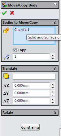
If you are looking at what appears to be assembly Mates, click on the button at the bottom that says Translate/Rotate and you will get the property manager above. In this property manager, all you have to do is click on the body and select the Copy option. Leave all the other inputs as zero and hit OK. SOLIDWORKS will prompt you with this message, since it thinks you forgot to do something

Just click OK and you will end up with two solid bodies that occupy the same space. This will be apparent if you look at the top of the Feature tree and the Solid Bodies Folder.

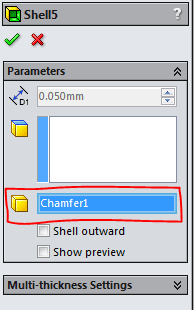
For our purposes, you may wish to hide the original for a minute by clicking on it and then clicking on the glasses icon. Now we will create the coating thickness by shelling out the copied body. In the Shell feature, we can enter the coating thickness and select any faces that might be masked during the coating operation (so the machined value is the final value) or leave the Faces to Remove box empty if all faces are getting coated. If the faces to remove box is blank, don’t forget to fill in the Solid Body box so SOLIDWORKS knows which body to apply the shell to.
Now that you have the shell that represents the coating, we have to subtract the coating from the original. We will accomplish that with a Combine feature with the Subtract option. The Combine feature is found in Insert > Feature > Combine and the property manager will look like this:
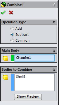
The Main Body is the original part and the Bodies to Combine is the shelled version of the copied body. Once this step is completed, the part is now shown in its pre-plate condition. You will be able to create drawing views of the machine operation and any pre- or post-plate inspection reports by using configurations to suppress or unsuppress the Copy/Shell/Combine features.
Once you’ve run through this once, you will find it to be an easy process.
For more training and tutorials on the many 3D CAD Modeling solutions in the SolidWorks family of products and add-ons, register for an upcoming Event or look into our SOLIDWORKS training.