Need to Know a Force but Only Have a Value for Displacement? No Problem.
As engineers we face common force control problems throughout our design process. Designing a deck? We can calculate the dead load based on number of people, furniture, materials etc.. Designing a door handle? We can estimate the amount of force an adult would apply. Designing a fan blade? We know the torque applied by the motor. The above are examples of force applied problems. We give the software the load (force, torque, pressure) and we receive insight into the stress, strain, and displacement resulting from the load. This is the common application we think of when using Finite Element Analysis(FEA). However what happens when we need to know a force but only have a value for displacement? With SOLIDWORKS Simulation this is no problem.
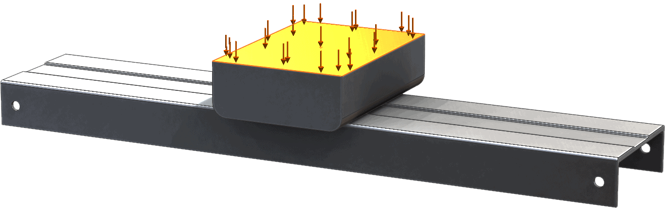
Let us take the following scenario into consideration. As a design engineer for a ladder manufacturer the load rating for the typical ladder is 200 lbs. When designing the step extrusion a 250 lb load was used and a Factor of safety(FOS) of 1.75 was required. Both design requirements make the design conservative. Engineers like conservative. The analysis looked like the following:
A 250 lb. force is applied to a rigid pusher block transferring the load onto the top of the step. The step is restrained using hinges at the pin locations and constrained normal to the ends where the step would meet the ladder frame. This analysis is a typical example of force control problem in Simulation.
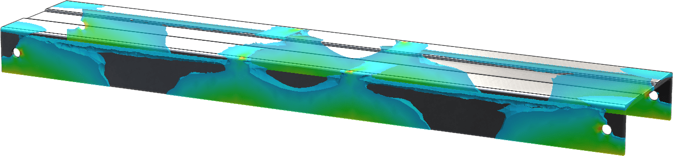
The results showed a FOS of 1.95 and an overall displacement of 0.0625″. The analysis results meet and exceed the design criteria. A fatigue analysis would then be used to verify the life of the product. Based on this knowledge the step moves to functional testing and then to production.
Soon after a ladder was returned with a step deformed by a quarter of an inch downward in the center. Now it is up to the engineer to figure out what happened. Was it a design flaw? Was it misuse?
If we were to take a classic approach to the problem we could incrementally apply a force until a quarter inch displacement is reported. This could be time consuming and hard to narrow down a force value that results in the exact known displacement.
What if we can prescribe a known displacement and let Simulation determine the amount of force required to deform the step? We can and it is easier than you think. SOLIDWORKS Simulation has always contained the option to prescribe a displacement as a load however most users did not know about it because it was buried in the fixtures category(Reference Geometry) not the Loads. Recently SOLIDWORKS Simulation moved the prescribed displacement to the Loads section.
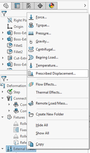
Using the boundary conditions from the original study. Use a Prescribed Displacement instead of the force. Note: a Non-Linear run is required for an analysis that has a permanent or plastic deformation. In this case there would be a permanent displacement of 0.25″.

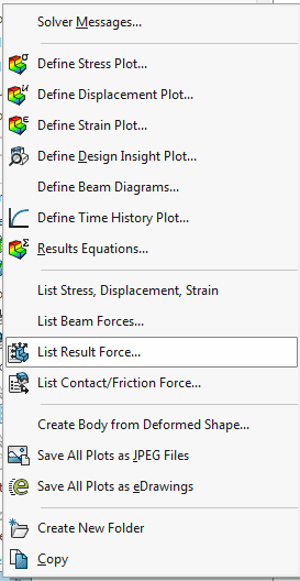
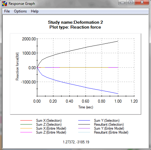
A reaction force can be obtained from the Simulation results by selecting the Results folder and choosing the “List Result Force” option. Select the face of the applied displacement. Simulation confirms that the force required to displace the step is much higher than the load rating of the ladder. 1832 lbs. are required to deform the step 0.25″. In this case misuse is the cause of the failure.
The perscribed displacment load condition gives applied load type flexibility to the user allowing the engineer to work with the information they have at hand. Simulation continues to prove to be a valuable tool helping make the designs smarter, better, and faster.