How to setup different gates in SOLIDWORKS Plastics
SOLIDWORKS Plastics
In the realm of injection molded parts, different shape and size gates and runners have to be used for parts that are either cylindrical, prismatic, or family of parts. If you’re testing only one part you have the option of creating a gate that fits the mold that you are wanting. There are several ways you can represent the gate. For example, you can use a split face, an extrude, or even model the whole runner and gate system.
Let’s look at an extrude to represent the gate. Now the size and shape I’m using is not realistic but only used to illustrate the point. The split face scenario works the same way as the extrude. All you really need the shape of the gate at the location you want to inject from so the depth of the extrude does not matter.
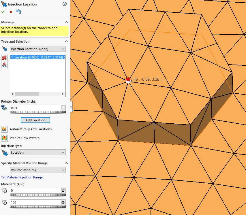
The first step is to create a shell mesh. When you create a shell mesh the injection location will be at the node of the mesh elements. SOLIDWORKS does ask you for the Pointer Diameter of the circular gate but that number doesn’t change the size of the gate. It will still be a pin point injection location.
Once a shell mesh is created, you will be given the option of creating a solid mesh. This software will now give you the option of sizing the gate to your liking.
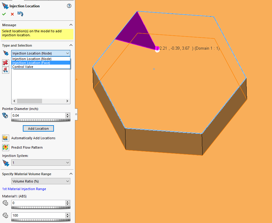
You can either set the Pointer Diameter for a circular gate or select the “Injection Location (Face)” from the drop down. Then all you have to do is select the element faces on the extrusion.
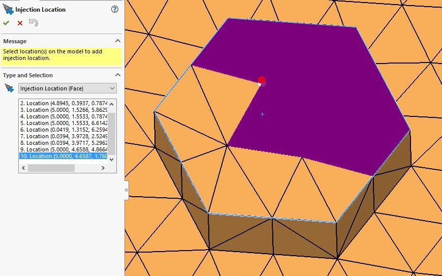
This will make the entire face the injection location.
Ketul