Simulation Results Overlay! Sweet Looking, Great Feedback.
Every year SOLIDWORKS releases a What’s New list jam packed with enhancements based on customer requests. One of the coolest and useful enhancements for SOLIDWORKS Simulation is the Simulation Results Overlay. Located under the title “Display Simulation Results in SOLIDWORKS Graphics Area” in the What’s New PDF. SOLIDWORKS only gives us 4 sentences on this enhancements but I thought it deserved several more than that.
So what is the Simulation Overlay and why is it such a good enhancement? The overlay does more than just graphically put Simulation results into the model view, it actually “replaces” the part with the deformed Simulation results showing the stress, displacement, FOS etc. plot as well. To access this new enhancement there is one caveat that needs to be followed.
The study for the part(s) you wish to display needs to be analyzed is at the assembly level. Simply Start a new study and “exclude from analysis” the part(s) you do not want analyzed. This leads to a study at the assembly level of just the components you want to show.
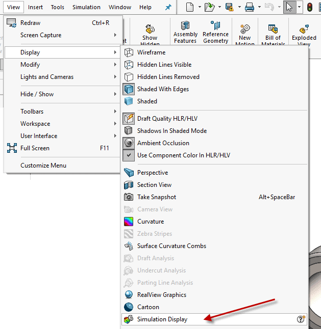
Once the analysis is complete save the file set. Switch to the “Model” tab as this is a SOLIDWORKS display setting. Choose “Simulation Display” from the View toolbar.
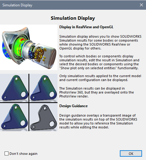
The user will recive a message indicating the use of this new feature.
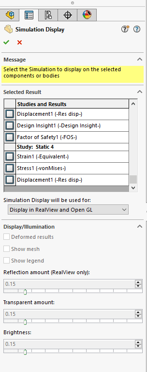
The Simulation Display property manager opens and the user has access to the Study results they wish to overlay. Transparency, Brightness, and Reflection can be controlled. Note: The deformed result is based on the Simulation Study’s settings.
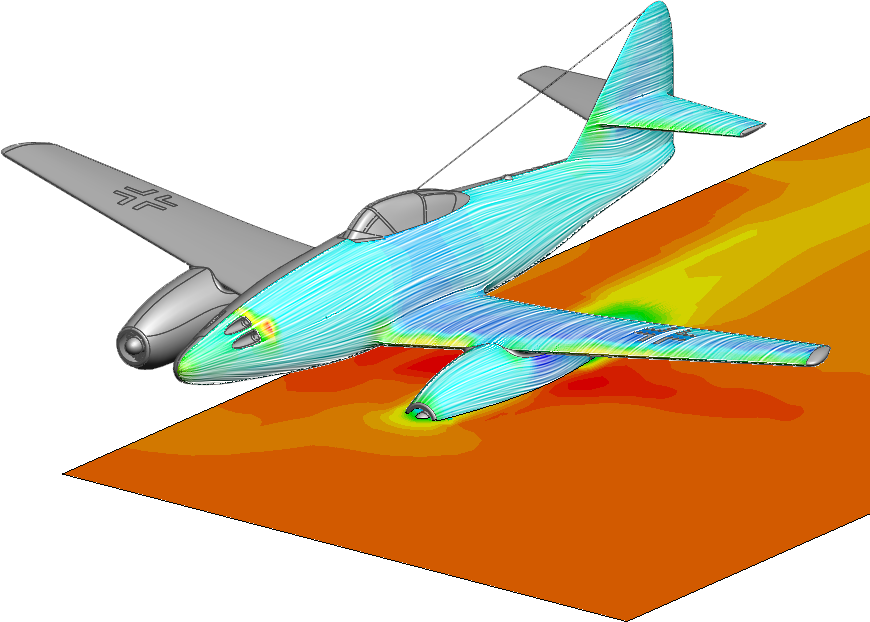
The result is an overlaid (replaced part) simulation result in the upper level assembly. Cool looking as well as an indicator of interference, form, fit, and function.
Above is what the Simulation Overlay is and how to create the resulting display. But, Why is this an enhancement that I think deserves more than 4 sentences? Because before this enhancement these types of displays were hard to achieve, and required other software such as Adobe’s Photoshop. An additional skill set would be needed to composite the Simulation result plot and the assembly screen captures together. This was an undertaking, and took a good deal of setup and time. Every orientation required two or more screen captures. With the results being overlaid in the 3d model any view is now possible incredibly quick. Now everyone can produce these awesome images, not only for marketing and reports, but for the full 3d affect checking clearances, fitment etc.
Let us know how you like this new enhancement, and send us some of your output images! I am always excited to see customers using new enhancements.