SOLIDWORKS: Nonlinear Material Models in SOLIDWORKS Simulation
Nonlinear Material Models in SOLIDWORKS Simulation
If you are using SOLIDWORKS Simulation Premium, you have access to the Nonlinear study type. One of the advantages of this study type over the Linear Static study is the ability to apply loads and boundary conditions that vary over time. Another is the access to multiple material models that represent nonlinear material behaviors:
- Nonlinear Elastic
- Hyper-elastic
- Elasto-plastic
- Super Elastic Nitinol
- Linear Visco-elastic
- Creep
Let me give you a brief description of each.
Nonlinear Elastic Model
For those materials that don’t exhibit any linear behavior, e.g., a stress-strain relationship like the graph below, the nonlinear elastic material model is appropriate. This material responds in a nonlinear way, even for small strains.
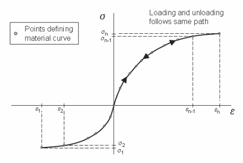
To incorporate this model, the Poisson’s ratio and a material stress-strain curve are required inputs.
Hyper-elastic Model
Materials capable of handling very large strain with relatively small stress can be accurately represented with this model. Rubber bushings and elastomeric sealing materials are good examples that typically deform significantly, even under small loadings. Their behavior is complex and depends on the way they are loaded. Testing to determine properties is usually required and the results are presented in the form of stress vs. stretch ratio for different test conditions, as shown below.
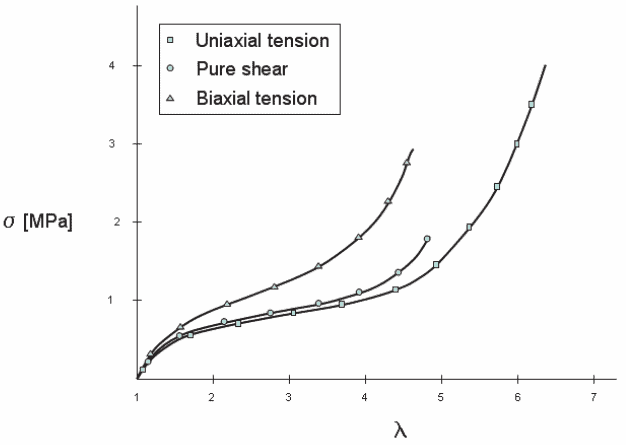
To incorporate this model, the Poisson’s ratio (between 0.48 and 0.50 for incompressible material) and several material constants are required inputs. The constants are derived from the stress-stretch ratio test data. Three hyper-elastic material models are available within SOLIDWORKS Simulation: Mooney-Rivlin, Ogden and Blatz-Ko. The first two are appropriate for incompressible rubber-like materials, while the third can be used for compressible materials like foam.
Elasto-plastic Models
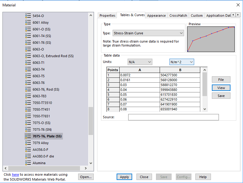
Materials of this type follow a linear elastic path during the early loading stages and switch to a nonlinear behavior at the onset of material yielding. Full behavior of these materials is provided via a stress vs. strain (SS) curve. The material library in SOLIDWORKS Simulation contains this curve data for some materials, as shown below for 7075-T6 aluminum plate.
Three elasto-plastic material models are available within SOLIDWORKS Simulation: Von Mises, Tresca and Drucker-Prager. The first two are appropriate for typical metallic materials. To incorporate these models, the Elastic Modulus, Poisson’s ratio and a material stress-strain curve are required inputs. The third model (Drucker-Prager) can be used to simulate granular soil material such as sand and gravel and requires two inputs: the angle of internal friction and material cohesion strength.
Super Elastic Nitinol Model
Shape memory alloys such as nickel titanium are a special class of materials with the ability to withstand high strains (up to about 20%) without permanent set after the loads are released. Their stress-strain curves exhibit several linear plateaus during the loading and unloading cycles as shown below.
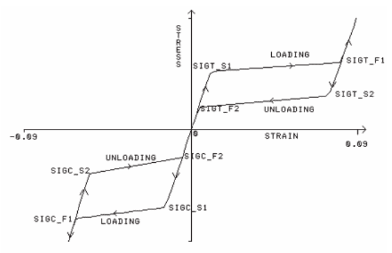
To incorporate this model, the Elastic Modulus, Poisson’s ratio and a material stress-strain curve are required inputs.
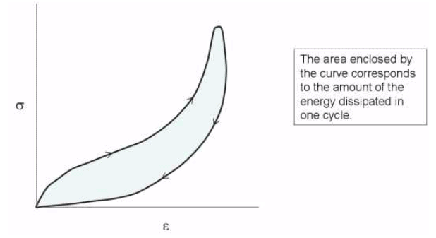
Linear Visco-elastic Model
This family of materials, typically used for vibration isolation, dissipate the mechanical energy induced during loading/unloading through viscous effects. Their behavior is dependent on the rate at which loads are applied and released as related to two primary parameters, the shear and bulk modulus relaxation functions. To incorporate these models, these time-dependent functions (or discrete representative points) are required inputs.
Creep Model
When exposed to elevated temperatures at constant stress states, materials can show increased strain over time. The graph below shows the three stages associated with creep strain (Primary, Secondary and Tertiary). At the end of the Tertiary range, the “x” represents the point of material failure at the rupture time (tg).
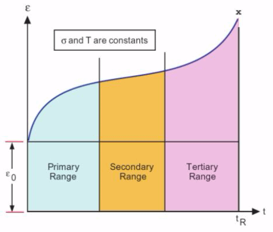
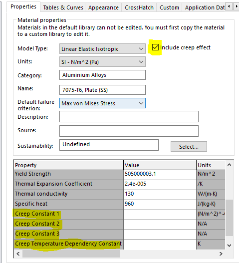
SOLIDWORKS Simulation incorporates the Bailey-Norton power law to calculate the uniaxial creep strain in terms of stress, time and temperature for the Primary and Secondary ranges. Assumptions are made to extend this calculation to multiaxial creep. To incorporate the additional calculation of creep strain, use the check box in the material editor window and include the 4 required constants (C0, C1, C2, Ct) to define the power law relationship for the material.
I hope this information sheds some light on the available nonlinear material models in SOLIDWORKS Simulation and encourages you to make use of this advanced capability to increase the accuracy and fidelity of your analysis projects.
Kurt Kurtin
Application Engineer
Computer Aided Technology