SOLIDWORKS: Simulation Beam Elements with Non-Planar Bonds
Simulation Beam Elements with Non-Planar Bonds
Recently I came across an issue bonding beam elements to non-planar faces on a body meshed as solid. It seemed like good information to share. Below is a simplified model of the model that was being simulated using SOLIDWORKS Simulation:
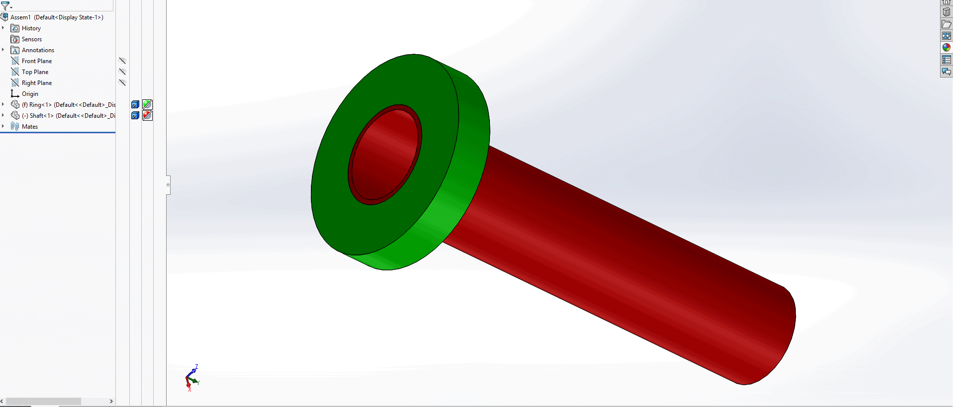
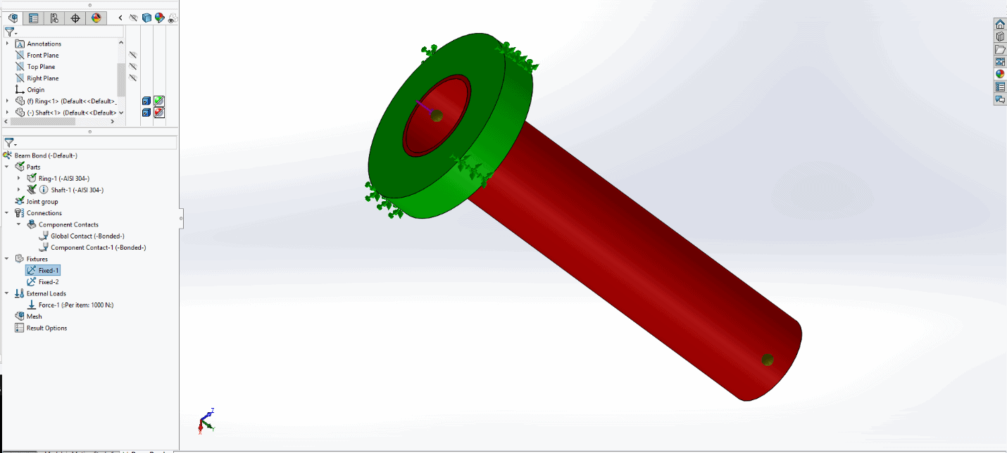
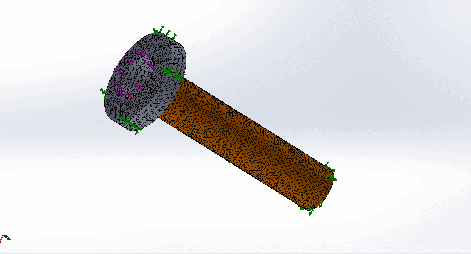
The red shaft was being treated as a beam element and loaded axially. The bottom of the shaft was fixed and the outside ring of the green body or “ring” as I will refer to it is fixed as well. The two parts in the assembly are bonded where the outer face of the shaft meets the inner face of the ring. The setup of loads and fixtures and the proof of bonded contact will be displayed in the pictures below respectively:
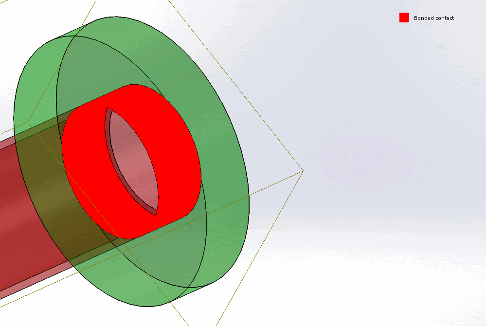
Bonded Contact
The setup was simple, but something interesting happened upon solving the study: it appeared that what was interpreted as a bonded contact was not truly being represented as bonded. The shaft only seemed to bond itself to a few select elements on the inner face of the ring. Re-meshing with different parameters and deleting the global contact and redefining the contact between the parts did not seem to have an effect. The shaft showed expected stress results, but the stress results in the ring still showed high stress areas in particular areas of the ring as opposed to being evenly distributed throughout the cylindrical face. See results below:
Beams Stress looks how one would expect being fixed and the top and loaded axially:
=
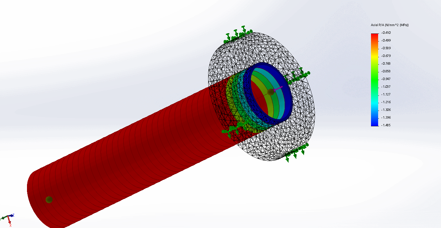
Ring stress has local areas of high stress when it would be expected to be evenly distributed throughout the inner ring:
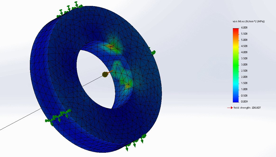
This came as quite a surprise. After some research and investigation, it became clear that beam elements are highly idealized. When defining a bonded contact between a beam element and a solid face, the program projects the beam nodes in a direction perpendicular to the face (which becomes quite complicated when using non-planar faces). So, in this case, the beam node was only projected and bonded to a few select nodes the inner surface of the ring; causing high stresses in those areas.
To still get an accurate analysis without increasing computation time too much, a simple conversion of the beam body to a shell type mesh yielded much more promising results.
Solid and Shell Mesh
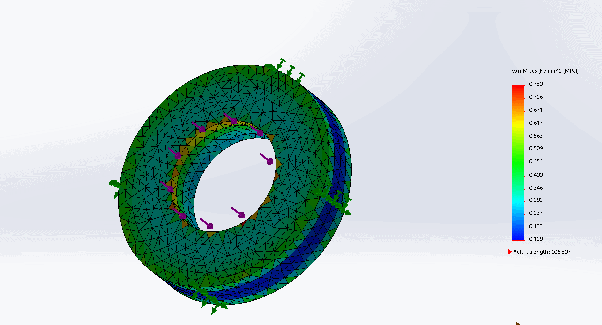
Stress results on the ring
As you can see, the stress distribution around the ring is much more even than before. This reminds me of the adage, “When you have a hammer, everything looks like a nail.” Just because we have the ability to use beam elements does not mean that they are always the best choice. This seems to be the case when bonding to non-planar surfaces.
Thanks for the read, and take a minute to check out some of our other great blogs!
Until next time,
Matt Sherak
Applications Engineer
Beam Elements with Non-Planar Bonds