Why You Should Use Simulation and 3D Printing Technologies Together
We often joke that simulation technology, also known as Computer Aided Engineering (CAE), and 3D printing technology are competitors. In reality, for product development, they are engineering partners. Each has its respective strengths and weaknesses.
It’s kind of like a buddy cop show. One has street smarts and the other is the brainy young whippersnapper. When they work together they solve tough crimes. Simulation and 3D printing technologies work together to help prevent engineering crimes: such as missing project timing dates and quality and performance issues.
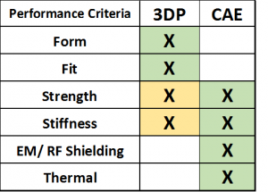 When comparing additive manufacturing techniques to its traditional predecessors, one challenge to anticipate is the contrasting differences in material properties. The chart to the left provides an overview of performance criteria and how 3D printing and CAE compare.
Each 3D printing technique yields a different set of mechanical and thermal properties, as well as layer bonding qualities which set it apart from components produced via an injection molding tool. Whether the material is a thermoplastic or a thermoset, these qualities will define its potential range of application opportunities.
FDM 3D printing technology and popular materials
Fused Deposition Modeling (FDM) 3D printing technology has the particular advantage of using true thermoplastics. This provides engineers with a range of materials to select from that will act similarly to production materials that they are familiar with. Popular FDM materials such as polycarbonate and Nylon 12 can be used for pre-production componentry, however, the layered quality of 3D printing yields anisotropic characteristics that differentiate how the part acts during a testing scenario.
Validating design performance virtually with simulation technology
This is where simulation helps us fill some predictive voids and prevents us from printing bad ideas. Granted, I would rather print a bad idea than mold or cast it from a soft tool. 3D printing is fast and costs have gone down, but stopping to evaluate your design performance virtually helps reduce wasted cycles at the printer AND provides more insight to performance in the field.
The ideal design validation workflow utilizes multiple predictive tools
Validating design performance is more than strength and stiffness which most SOLIDWORKS users associate with simulation. Simulation can also chip in when we need to verify other criteria such as electromagnetics or radio frequency shielding as well as thermal performance. In an ideal workflow we utilize all of our predictive tools: Simulate > 3D Print and Test > Simulate Some More > 3D Print and Test > Then Go To Tooling.
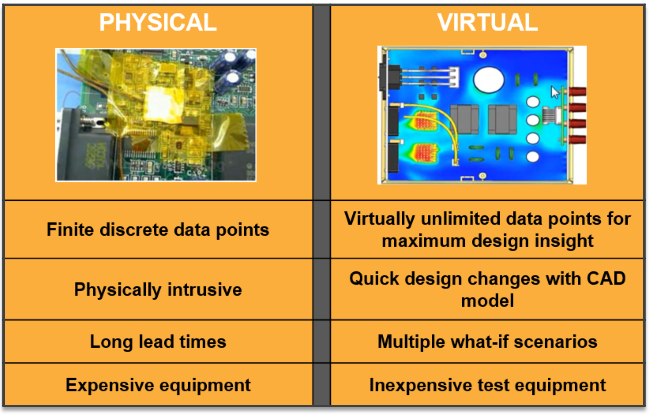
Even when we have tooled parts that are very close to production quality, virtual testing has some distinct advantages over physical testing. Specifically, it’s a perfect “noise” free environment where we can truly compare apples to apples designs. In addition, with simulation, we can visualize quantities such as fluid flow or stresses that are intrusive or expensive to quantify physically.
Physical Versus Virtual Testing Comparison
As printing and CAE technologies progress we are starting to see more areas where they co-exist and complement each other and make each other better.
In 2016, Stratasys debuted the J750 full color, multi-material 3D printer. This evolutionary additive manufacturing technology selectively deposits a matrix of thermoset resins allowing for a color palette beyond 360,000 color options.
It also has a wide range of materials for simulating shore durometer values that can be used for prototyping and bridge manufacturing applications. Using the J750, engineers can enhance their visual and tactile feedback of a prototype part during product development stages.
We can now use 3D printing to help visualize analysis results. Simulation has always been a great visualization tool but now we can “feel” those results and hold them in our hands!
Using simulation and 3D printing technologies for design optimization
Two of the most interesting advancements in CAE and 3D printing are tools for shape optimization. It’s valuable to run a single study for a single load scenario. That value goes up by orders of magnitude when you can automatically optimize across multiple use or loading cases using simulation technology inside tools such as solidThinking Inspire.
Optimization Workflow Using solidThinking Inspire
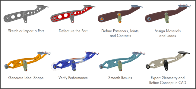
Topology optimization tools have been around for quite a while and in the early years, they were limited due to shape constraints for typical manufacturing methods. Then these codes got smarter to include provisions for manufacturing constraints to make sure the optimized design are feasible.
Now that 3D printing is becoming a manufacturing option it opens up the doors for shapes that we had to “throw out” before. Just like traditional manufacturing methods, there are process effects to consider.
Typical solidThinking Click2Cast Casting Simulation Outputs
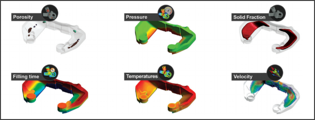
For decades CAE technologies have been used to predict manufacturing processes such as casting, molding and stamping. Now we can use simulation tools to understand the 3D printing process effects on the part performance.
3D Printinng Process Simulation Workflow
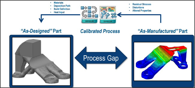
We could physically print hundreds of parts using different build paths and process settings but that soon becomes cost and time prohibitive. Simulation tools are now being used to take into account printing variables allowing engineers to predict 3D printing process effects on the final part.