SOLIDWORKS: Modeling Ball Bearings for SOLIDWORKS Assemblies
Modeling Ball Bearings for SOLIDWORKS Assemblies
Why is my assembly so slow in SOLIDWORKS?! Let’s continue on this idea. As I mentioned in my last article about modeling springs for assemblies, there are many things that effect performance in an assembly that are modeling related. Today we are going to take a look at a ball bearing.
There is a time and a place for detail. Having highly detailed parts for piece part manufacturing is perfectly acceptable and necessary. Placing highly detailed parts into large assemblies can cause severe performance issues.
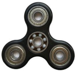
I see bearings placed in many assemblies. They are usually inserted as a single part file with multiple bodies. Many of these are modeled in such a way that it appears to be a basic part from the outside.
Let’s take a look at a sample file:
Using the assembly visualization tool on this file, I took a look at the file size and graphics triangles.
Our initial file size is 667 KB. but our Graphical triangles to display this is 52212.
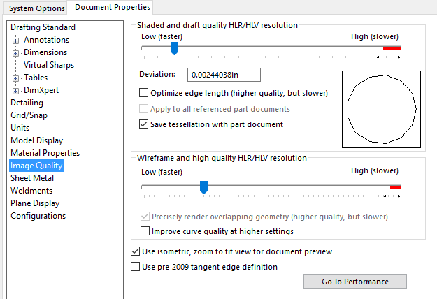
We also want to take a look at the image quality. The slider should be between ¼ and ½ of the way from the left side. Moving the slider to the right end (Red Zone) will cause exponential file size growth.
Why do we have a small file size, but have a very high triangle count? This is just a cylindrical extrude!
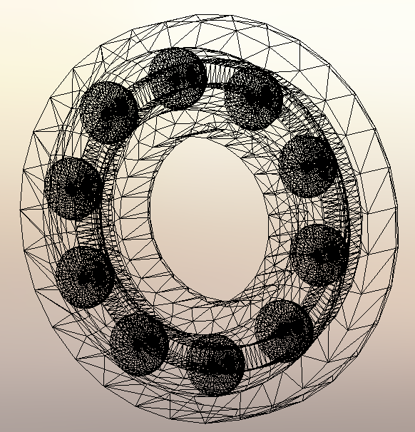
When you look at the solid bodies folder, and take a cross section of this part, the mystery quickly unravels.
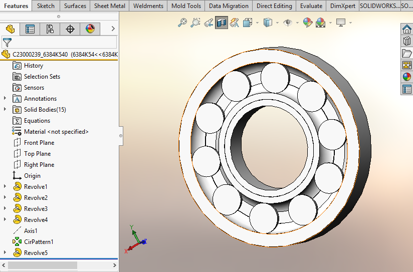
All of the individual balls were modeled into this part and are completely internal to the geometry. So, why does this make a difference?
When we mesh the file, each of the spherical balls requires a very high number of triangles to generate.
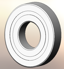
To simplify this geometry, I am going to create a new configuration called SIMPLIFIED, and I am going to extrude a solid cylinder thru the bearing to merge all bodies into one solid body. The inside of the bearing will never be seen in an assembly. This will reduce the curvature geometry that needs to be calculated.
On this part, I created a sketch on the face of the recess. I am going to create 2 circles. The first circle is going to be offset .02 from the outer edge. The second circle is going to be converted from the ID.
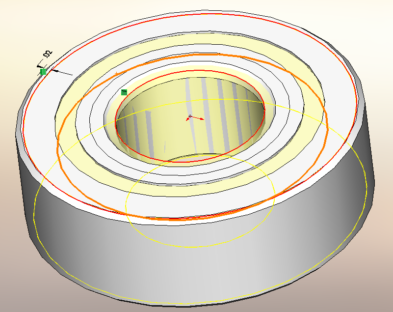
Now we extrude this up to surface; selecting the face of the groove on the back side of the part. Make sure you merge the result.
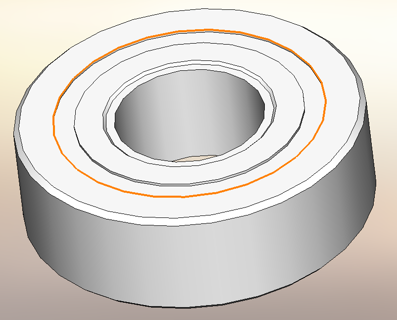
The result is a bearing that looks exactly the same as before, except the geometry is completely solid.
The new file size is reduced to 135 KB (80% reduction). More importantly, the graphics triangles were reduced to 18180 (65% reduction)
So by merging the internal geometry into a single solid block, we can get significant file performance improvements. Just make sure when you insert your bearing into the assembly that you use the simplified configuration.
Hope this helps.
Bryan Pawlak
Sr. Application Engineer
Computer Aided Technology