SOLIDWORKS: Making Sense of Simulation Meshing- Part 2
Making Sense of Simulation Meshing- Part 2
Welcome to part 2 of the 3 part series about mesh considerations in SOLIDWORKS Simulation. In part 1, we covered some high-level considerations and adaptive meshing. If you missed part 1, view it here. In this post we will discuss some mesh quality tools SOLIDWORKS Simulation has to offer. In the last post we will discuss different types of elements and meshes for Finite Element Analysis (FEA, FEM).
Moving on, knowing if your FEA mesh is a good quality is essential to accurate studies using SOLIDWORKS Simulation. Luckily, SOLIDWORKS has supplied us with some great tools for interrogating the mesh too determine it’s overall quality.
- Mesh Quality Plot: Once a mesh is created in SOLIDWORKS Simulation, you can define a mesh quality plot (right Click the mesh-> create mesh quality plot). There are a few types of plots to choose from:
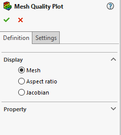
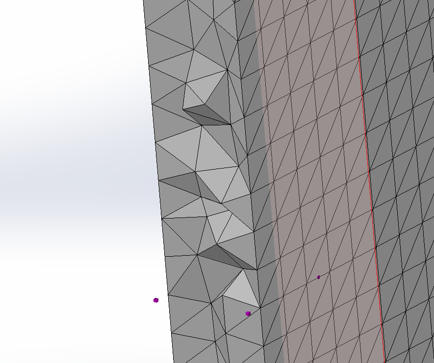
- Mesh: Shows the mesh and their edges. Useful in conjunction with a mesh sectioning to see internal elements. Below is a picture of a sectioned mesh, so that internal elements can be seen.
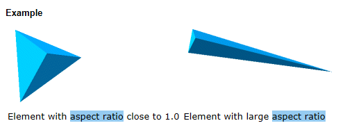
- Aspect Ratio: Aspect Ratio is a good measure of element quality. The perfect tetrahedron has an Aspect Ratio of 1.0, and the larger the aspect ratio, the less ideal the element. Typically, a very small percentage of elements with an Aspect Ratio>10 is desired.
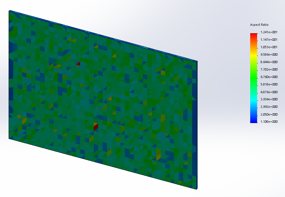
Below is an Aspect Ratio Plot of a very thin plate. There are some distorted elements that show up as yellows and reds.
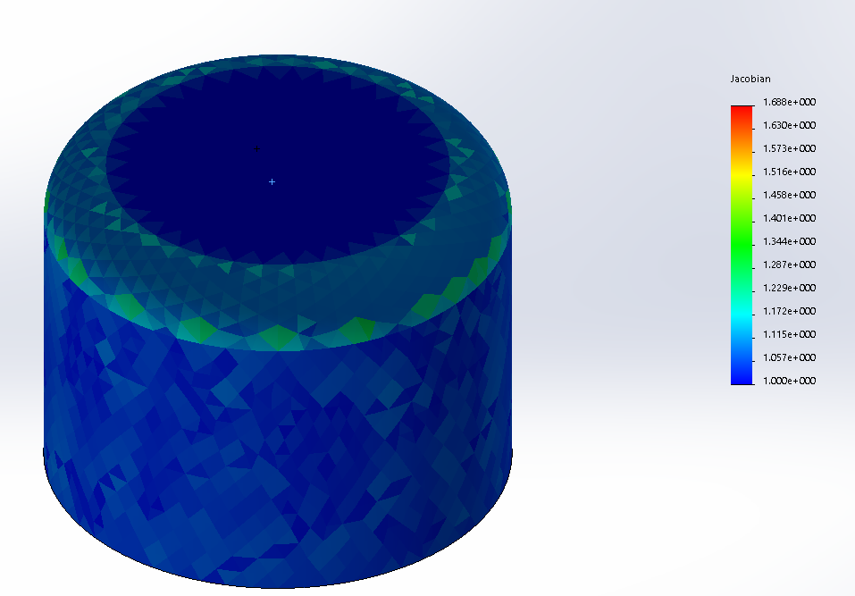
- Jacobian: Only available for high quality (2nd order) elements. These types of elements are much more adept at capturing curved geometry, but small areas of high curvature can pose problems. A perfect Jacobian element has all mid-side nodes located exactly at the middle of straight edges. The Jacobian ratio is a complex subject. Essentially, the ratio increases as curvature of the edges increase. Jacobian Ratios of 40 or less are acceptable.
See below an example of a Jacobian plot. Notice the higher Jacobian values in the more curved areas of the model.
Thank you for taking time to read this blog. Stay tuned for part 3 in this series where we will talk about different types of meshes available in SOLIDWORKS Simulation.
Making Sense of Simulation Meshing – Part 1
Thank You,
Matt Sherak
Simulation Application Engineer
Computer Aided Technology