Creating 3D Free Surface SOLIDWORKS Flow Simulation Output
How well do you know your Property Managers in SOLIDWORKS, SOLIDWORKS Simulation or SOLIDWORKS Flow Simulation? Do you really pay attention to all the buttons and options that you can use for any specific feature? Chances are, if you’re like me, you looked at all the bells and whistles the first time or two and then quickly forgot about each available option. We tend to learn exactly what we need to know, get good at that, and move on. Which brings me to the theme of this blog. How do I use the existing tools available for creating interesting and engaging output with SOLIDWORKS Flow Simulation? The best analysis in the world is only as good as the output and message that can be created from the results.
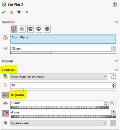
Not too long ago I wrote the blog “Which will fill first?” using SOLIDWORKS Flow Simulation 2018’s new feature “Free Surface Flow”. Looking even further into the past, I wrote about the SOLIDWORKS Flow Simulation tool “Transient Explorer“. Since the release of SOLIDWORKS Flow Simulation 2018, I’ve been investigating additional uses of these tools to create appealing results. As it turns out, a feature for creating 2D cut plots, that has been available for ages, was just what I was looking for. That feature is ‘3D Profile’ under the Contours section of the 2D Cut Plot Property Manager.
Honestly, I do not remember when I first used the 3D Profile option for a 2D cut plot in SOLIDWORKS Flow Simulation. It was a button to click and something to look at but was quickly forgotten. Recently though, when trying to create a few “wow factor” visuals for a project, I found that this old tool fit the bill perfectly. All it took was turning on this Property Manager button and investigating a few of the options. Here is how it works for the visual results I created.
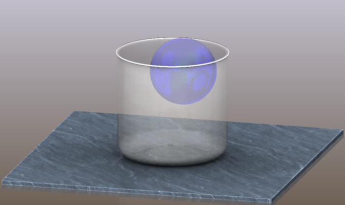
I wanted to show how SOLIDWORKS Flow Simulation Free Surface analysis would solve the dropping and sloshing of water into a beaker. I set up a multibody part model that included a 1L glass beaker, a table surface, and a 250mL bubble of water suspended above the bottom surface of the beaker.
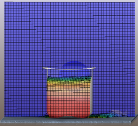
With my CAD model set up, I began creating the SOLIDWORKS Flow Simulation project. For this analysis, it requires turning on the Free Surface analysis option, setting up the analysis as a 3 second transient study, turn on gravity acting in the appropriate direction, and specifying air and water as the immiscible fluids. Continuing the setup within the Flow Simulation project, I added a Local Initial Mesh to a volume surrounding the beaker. I also added Global Goals to track the average mass fraction of both water and air. Then it was just a matter of creating the CFD mesh and solving the project.
Once solved, I created a Cut Plot of the results using the assembly’s front plane as a reference. I want to display color contours of the mass fraction of water with 30 levels of color. Occasionally I would make the result plot slightly transparent but most of the time, this is where I would have stopped in creating the visual output. This works for an instance in time, but I want more!
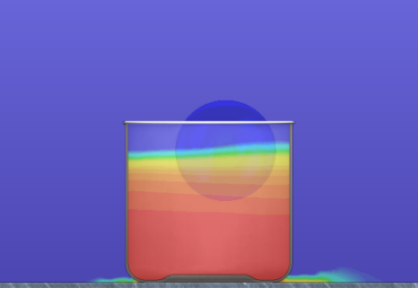
This is where the additional post-processing capabilities of the Transient Explorer tool, with additional Cut Plot options, comes into play. Continuing with the Cut Plot setup, I turned on the option for 3D Profile. You need to specify a distance for the 3D contours and, optionally, turn on a grid and spacing, and then position the CAD model into an orientation so the depth can be easily seen. This is a good start for visualizing this specific result at a single moment in time.
With the Cut Plot set up the way I want, I then focused on using the Transient Explorer tool to really make this result effective. Transient Explorer loads all the saved time steps of data that I originally specified and allows the playback of those results. I only need to save the animation of the water splashing into the beaker for the visual effect I am after.

The animation of water splashing into the beaker conveys how Free Surface can solve water sloshing into a container. Digging into the available tools of the Cut Plot Property Manager – finding the old that became new again – allowed me to produce the visual I needed. The 2D Cut Plot is great for showing an instance in time for a Flow Result. Adding in the 3D Profile with depth and using Transient Explorer to animate the result was allowed me to create the final visuals to show the dynamics of the event! The next time you need to create awesome visual output in SOLIDWORKS Flow Simulation, be sure to look at the tools that might already be available to you within a Property Manager. Now go make your products better with SOLIDWORKS Simulation!
Bill Reuss
Product Specialist, Simulation
Computer Aided Technology