Abaqus Contact Quirks: Automatic Shell Thickness Reduction and You
 Fig. 1: Contact animation
Left: Automatic thickness reduction permitted Right: Automatic thickness reduction overridden
“Why isn’t my contact engaging? It obviously should be!”
“Why is Abaqus changing my shell thicknesses? I didn’t ask it to!”
These are frustrating questions in what should be a straightforward general contact analysis. If you are seeing strange shell element contact behavior in your Abaqus/Explicit analysis, you may be experiencing some automatic corrective behavior that is inappropriate for your scenario. It can, however, be easily monitored and controlled to achieve an accurate solution. Read on to find out how.
1. Verify you have the problem.
Look for the following warning in your STA file:
***WARNING: In step 1, some facet thicknesses for general contact were reduced from the parent element or specified values due to a large thickness compared to facet dimensions. The most significant thickness scaling factor was 0.21213 for a facet on parent element 1 of instance PART-SHELL-1. An element set named “WarnElemGContThickReduce” has been created to locate the regions of reduced thickness.
2. Why is this happening?
General contact is a convenient way to define contact in an explicit finite element model. By default, general contact automatically considers all exterior surfaces as having the potential for self-contact. However, for models containing shell elements with mesh density similar or less than their thickness, their inclusion in the self-contact domain will trigger automatic thickness reduction. This measure is meant to avoid erroneous contact engagements related to shell thickness overlap. This thickness change pertains to only contact clearances, and NOT stiffness calculations.
It is covered in the documentation in the Abaqus Analysis User’s Guide, 36.4.5 Contact controls for general contact in Abaqus/Explicit:
Control of contact thickness reduction checks
By default, the general contact algorithm requires that the contact thickness does not exceed a certain fraction of the surface facet
edge lengths or diagonal lengths. This fraction generally varies from 20% to 60% based on the geometry of the element and whether the
element is near a shell perimeter. The general contact algorithm will scale back the contact thickness automatically where necessary
without affecting the thickness used in the element computations for the underlying elements.
To check whether the thickness needs to be reduced in any particular region in the model, the contact algorithm first assigns the full
thickness to each contact node, represented by a sphere centered at the node with a diameter equal to the thickness. Next, the thick-
ness is reduced so that the spheres do not overlap with any neighboring facets that are not attached directly to the node, preventing
spurious self-contact from developing. Then, the nodes on the perimeter of shells are moved a maximum of 50% of the facet size in the
plane of the facet away from the perimeter to eliminate the “bull-nose” effect that occurs with the contact pair algorithm (see
“Assigning surface properties for contact pairs in Abaqus/Explicit,” Section 36.5.2). If the thickness of the shell perimeter nodes is
greater than twice the maximum perimeter offset, a final thickness reduction is performed to eliminate the remainder of the “bull-
nose.”
Hyperlink to this section in the official 2019 SIMULIA manual (requires DS login)
3. How can I prevent it?
The manual says the following:
If the default thickness reductions are unacceptable in particular regions of the model, you can exclude self-contact for those regions via contact exclusion definitions (see “Defining general contact interactions in Abaqus/Explicit,” Section 36.4.1) and activate a control for the contact thickness reduction checks.
To accomplish this, first create a contact surface (named “Excl-Shell-Surf” in our example) containing the facets you’d like to exclude from the self-contact domain. Add an exclusion card for it to the contact definition:
** Interaction: Int-1
*Contact
*Contact Inclusions, ALL EXTERIOR
*Contact Exclusions
Excl-Shell-Surf,
*Contact Property Assignment
, , IntProp-1
Add a new contact control assignment parameter to the contact definition block:
** Interaction: Int-1
*Contact
*Contact Controls Assignment, Contact Thickness Reduction=NOPERIMSELF
*Contact Inclusions, ALL EXTERIOR
*Contact Exclusions
Excl-Shell-Surf,
*Contact Property Assignment
, , IntProp-1
See Abaqus Keywords Reference Guide, *CONTACT CONTROLS ASSIGNMENTfor more information on this parameter.
This parameter eliminates the thickness reductions in regions of the model that are excluded from self-contact, thus eliminating any shell contact thickness reductions in the surface “Excl-Shell-Surf”. Check the STA file to confirm that the earlier warning has disappeared as a result of these changes.
4. Can I monitor this kind of behavior through ODB visualization?
Yes! You can monitor any automatic shell thickness reduction by requesting and plotting the field outputs “STH” and “CTHICK”. STH is the assigned shell element thickness; it is the same as the thickness specified for the shell when the section/material properties are assigned to the part. To illustrate this, below, we have two example simulations. On the left is the model with default automatic thickness reduction allowed. On the right is the model with automatic thickness reduction overridden. They show the same STH values on the shell surface.
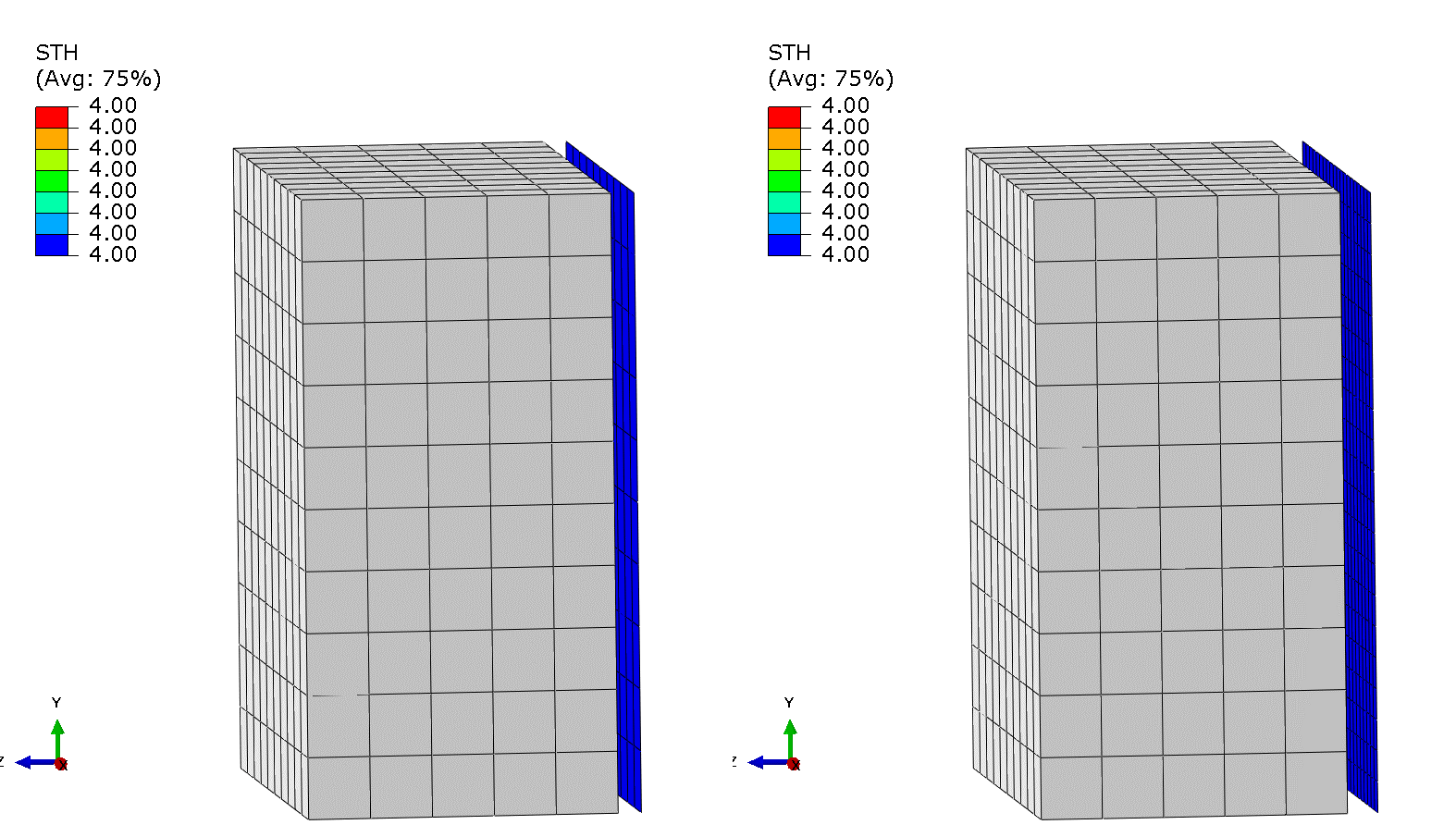
Fig. 2: Output of shell thickness as assigned
Left: Automatic thickness reduction permitted Right: Automatic thickness reduction overridden
On the other hand, CTHICK is the contact thickness of the shell element, or, in other words, the thickness the contact algorithm uses for contact enforcement during the simulation. Ideally, the user would want the two values to be the same. However, as discussed earlier, using the general contact algorithm can trigger reductions in the value of CTHICK as compared to the value of STH. Plotting these two variables can give an estimate of where the contact thicknesses have been reduced and by what amount.
These variables also act as verification tools to make sure that the fix proposed in this study is actually working. Below, see how the same simulations show divergent CTHICK values. As can be observed from this comparison of the STH and the CTHICK results, if the contact properties are not suitably modified, the CTHICK value will be lower than STH value leading, to inaccurate results. However, making the contact card changes discussed earlier insures that the STH and CTHICK values stay the same and the simulation results are credible.
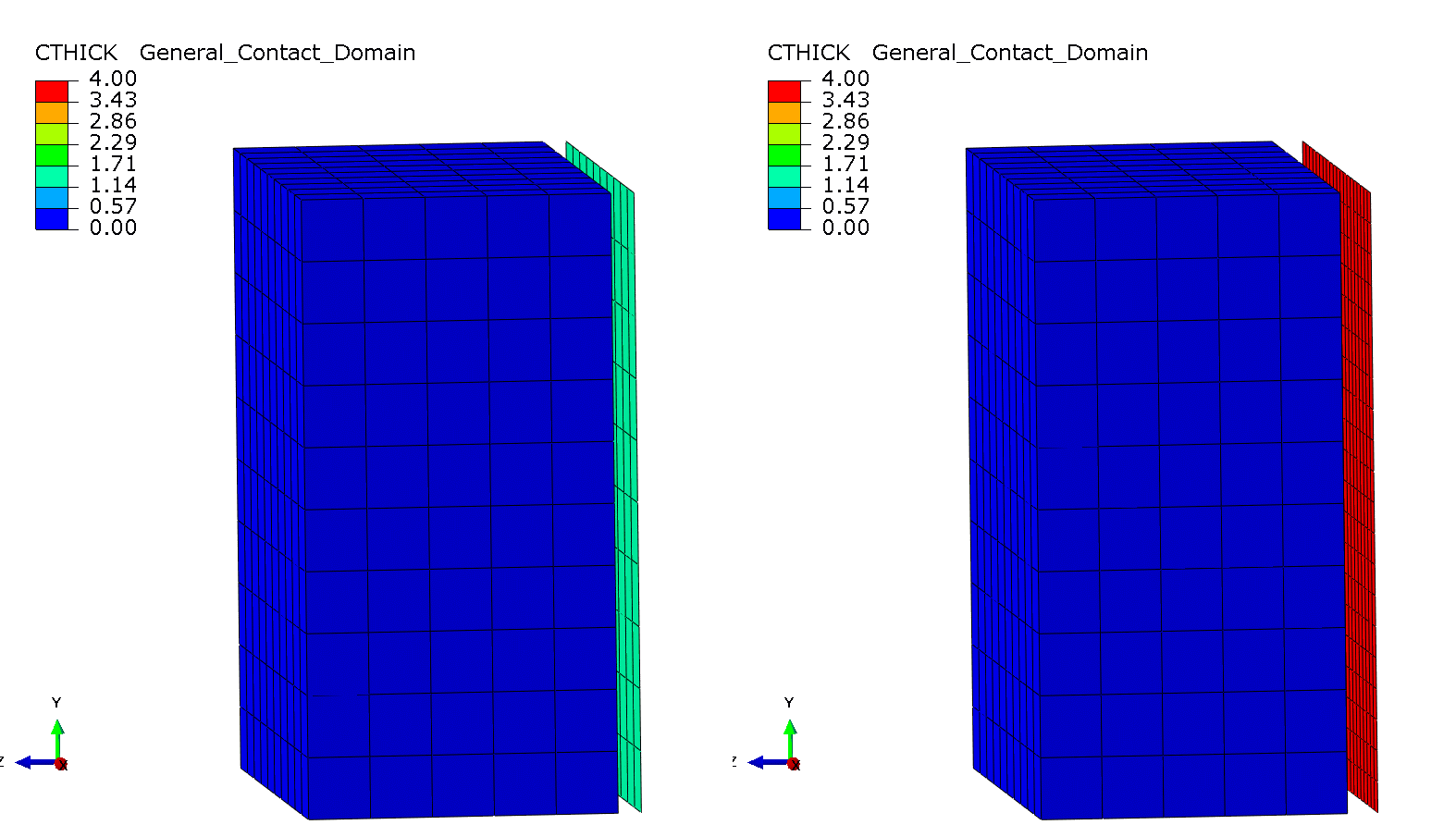
Fig. 3: Output of shell thickness according to contact algorithm
Left: Automatic thickness reduction permitted Right: Automatic thickness reduction overridden
You get far more than just software with CATI as your Dassault Systèmes SIMULIA reseller. You get the best deals from one of the most established partners. You get swift support from our consulting engineers at the ready. You get a wealth of implementation and execution knowledge and experience, because it’s what we’ve done every day since 2005.
To learn more about how CATI can accelerate your business and enable your engineers, contact us today!