SOLIDWORKS Simulation: Beam Joints
SOLIDWORKS simulation allows users to take advantage of beam elements in order to simplify studies using structural members like pipes, angle iron, etc. We will begin by defining what a beam element is and then defining beam joints. Followed by showing a tip on how to create joints for structures with welding gaps. Finally, we’ll conclude by releasing degrees of freedom at the joints and observe the changes in a displacement plot.
Beam definition
In SOLIDWORKS Simulation there are 3 different types of ways we can mesh bodies: solid, shell, and beam. The beam element is the simplest of the 3 because it is just a straight line with 2 nodes (see below).
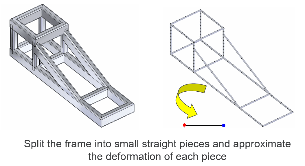
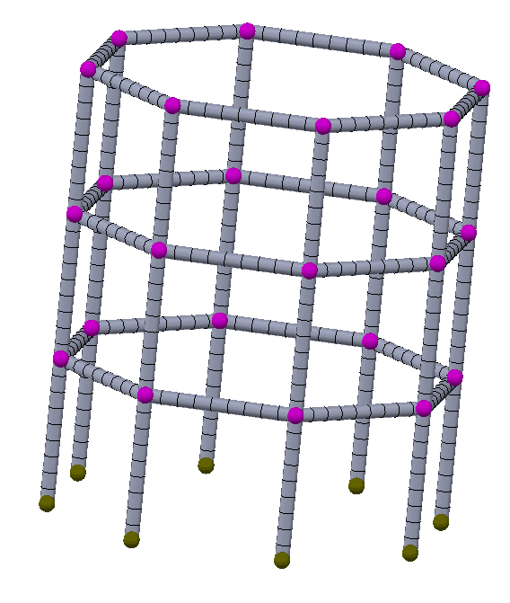
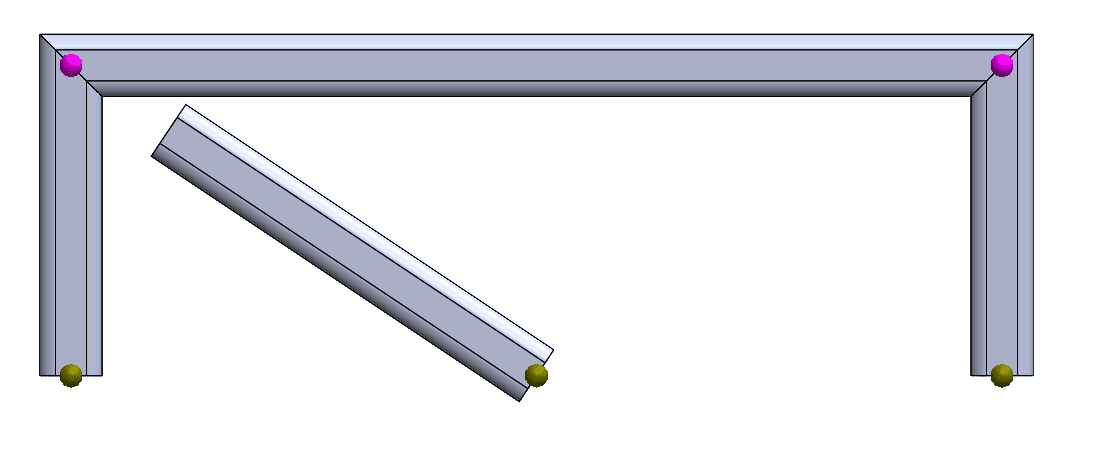
These beam elements combine together to define the structural members and have joints at their ends. These joints either join two beams, shown in pink, or define the end of a beam, shown in yellow (see image below).
Working with Weld gaps
Now that we know what joints should look like, please observe the joints in the picture below. What is going on at the join in the top left? 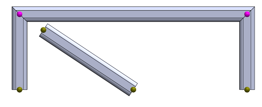
The top left joint is between the left vertical and the horizontal beams only and does not include the diagonal beam. Perhaps we left room for a bracket in this design but now we need this joint to accurately simulate this weldment. We need the joints to look like the weldment shown in the picture below.
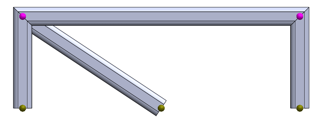
Fortunately, SOLIDWORKS has provided a way to account for non-touching beams. Simply edit the joint group and select the option for “less than” and then add a value. Keep in mind that we don’t want this value to be too large. If we chose 5 meters then the software will attempt to join all the joints in this weldment.
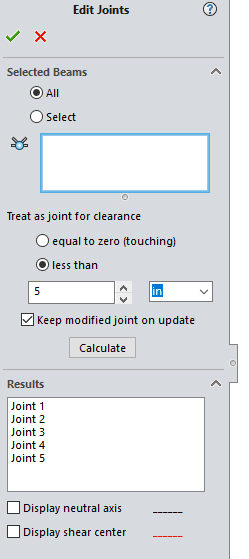
Once the clearance is assigned and the joint group is calculated you will notice that the diagonal beam only contains 1 yellow node and the other end is shown to be included with the pink top left joint.
Release Degrees of Freedom
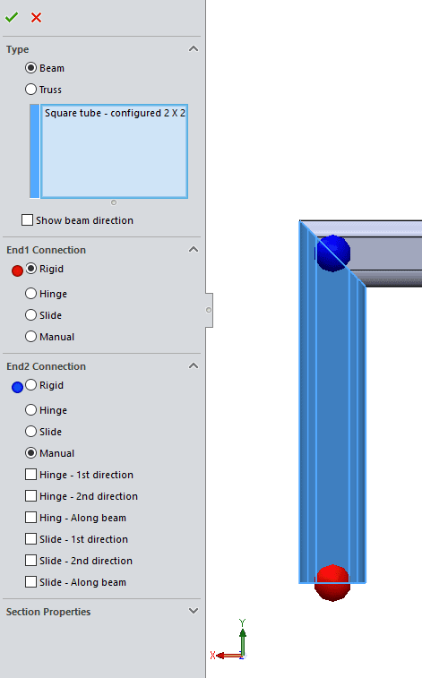
By default, each joint is rigidly defined. This can cause a structure to be stiffer in our analysis than it is in the real world. In order to adjust how rigidly beams are connected we need to edit the definition of individual bodies. First, notice the color coding. Let’s modify the blue joint that connects the 2 beams. Our options are Rigid, Hinge (release all rotations), Slide (release all translations), and manual (release 1 or more translation or rotation). Releasing a rotation or translation allows the beam to rotate or translate in the direction that was just released. Or directions in the case of the Hinge all 3 rotations are released. Likewise, for Slide, all translations are released.
Effects of released a degree of freedom
I created a study to visualize how these various joint definitions affect the stress and displacement of the overall model. The model is simply 3 square beams assembled in a c-shape and then patterned to show rigid (far left), slide (2nd from left), hinged (3rd from left), and then each of the 6 degrees of freedom individually released.
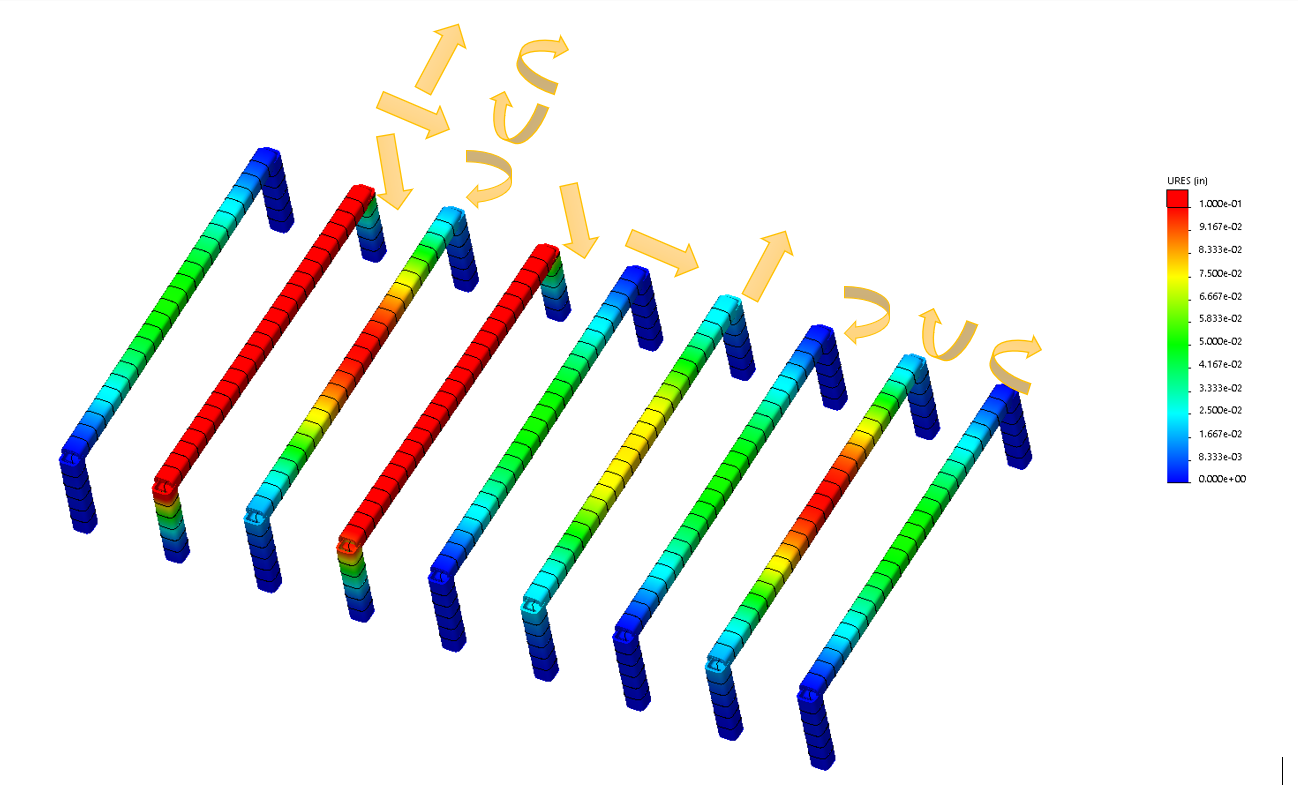
As we can see from this displacement plot, some degrees of freedom have no impact at all. This is due to the nature of the load. I loaded each beam with a force load in the vertical direction. The degree of freedoms that affected our plot the most were releasing translation in vertical (same direction as the load) and releasing rotation allowing the beam to allow rotation in the vertical direction.
Conclusion
Modifying the beam joints can have a large impact on the displacement and stress results. For all welding beam joints, the rigid connection should be used for the most accurate results. In order to simplify the simulation study, one could remove the universal or ball joint from the model and connect the beams together at a joint. Then the user could edit the joint and free up the translations or rotations by selecting hinge or slide joint.
Matthew Fetke
Application Engineer, Simulation
Computer Aided Technologies, LLC