Injection Locations: Two Ways to Apply
Injection locations are a hot topic in our blog series including Make Your Mark on Injection Locations in SOLIDWORKS Plastics Simulation, and SOLIDWORKS 2019 What’s New Plastics Geometry Based Boundary Conditions. I wanted to expand on this topic yet again and discuss the difference between Geometry Based injection locations, and Mesh Dependent injection locations.
Both Geometry Based, and Mesh Dependent injection locations do the same thing. The injection locations give the software a point of entry for the molten plastic to be injected.
Up to the 2019 release of SOLIDWORKS, Plastics Mesh Dependent injections locations were the standard and a mesh of the cavity was required before they could be applied. The injection location was applied to a node on the mesh.

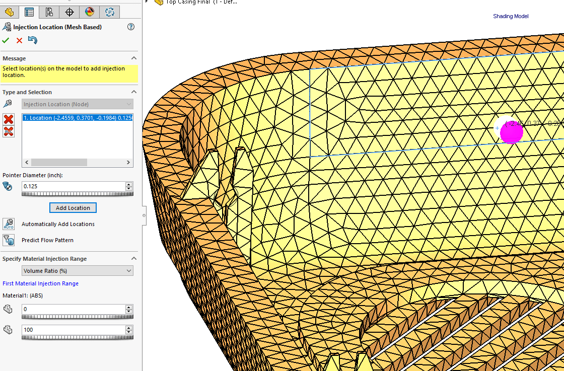
Use of split lines was required if you wanted an injection location at a specific location. The downfall of the Mesh Dependent injection location is that if the cavity was re-meshed the injection location was lost and had to be reassigned.
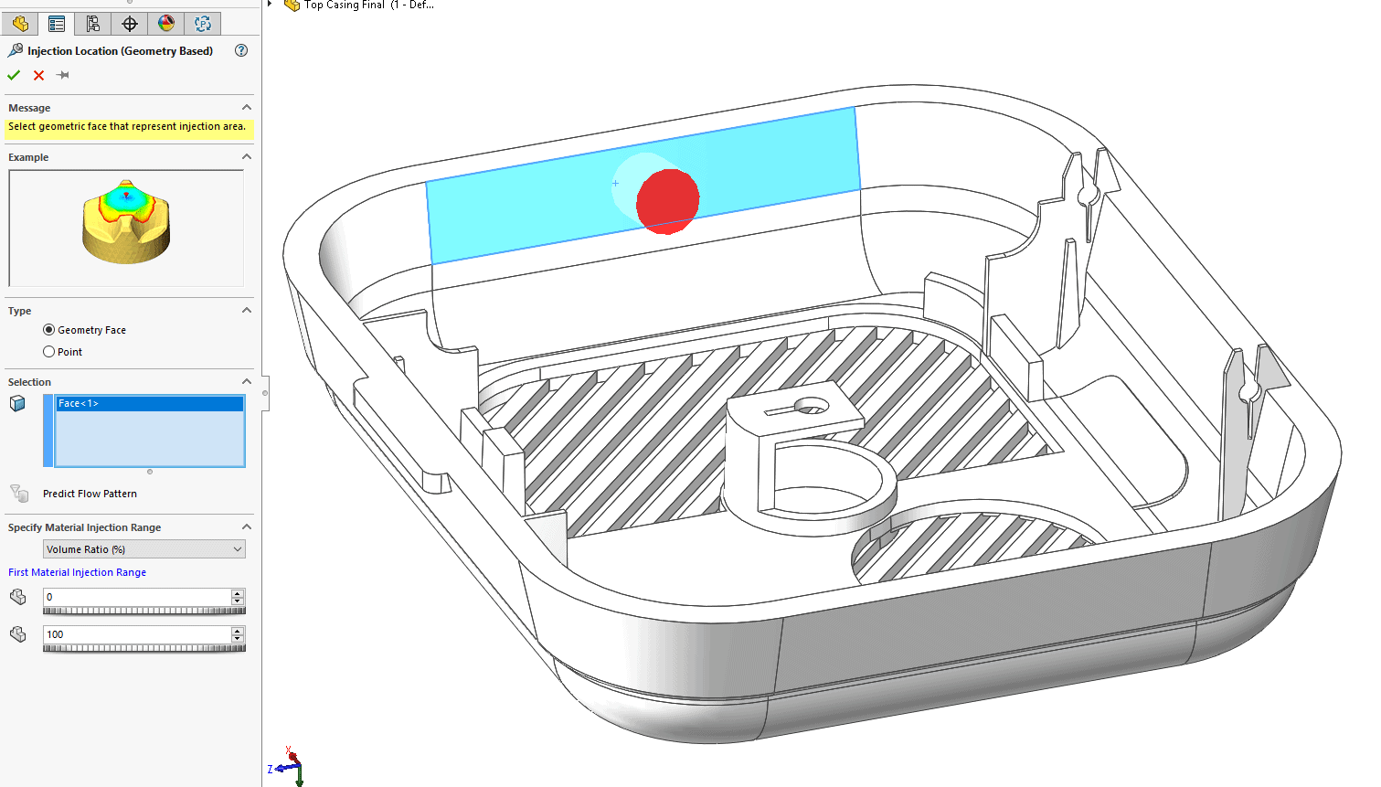
Geometry Based injection locations are applied before the mesh is created and applied directly to vertices or faces in the model.

The benefit is that the injection location stays on the part. The user can redefine the mesh without losing the injection location. A couple of things you need to consider with the Geometry Based injection location is that when selecting a face, the injection location is placed at the center of the face. The shift to using Geometry Based boundary conditions will grow in the future by offering the ability to copy studies to configurations, move just one boundary condition, etc. just like in the SOLIDWORKS Simulation product.
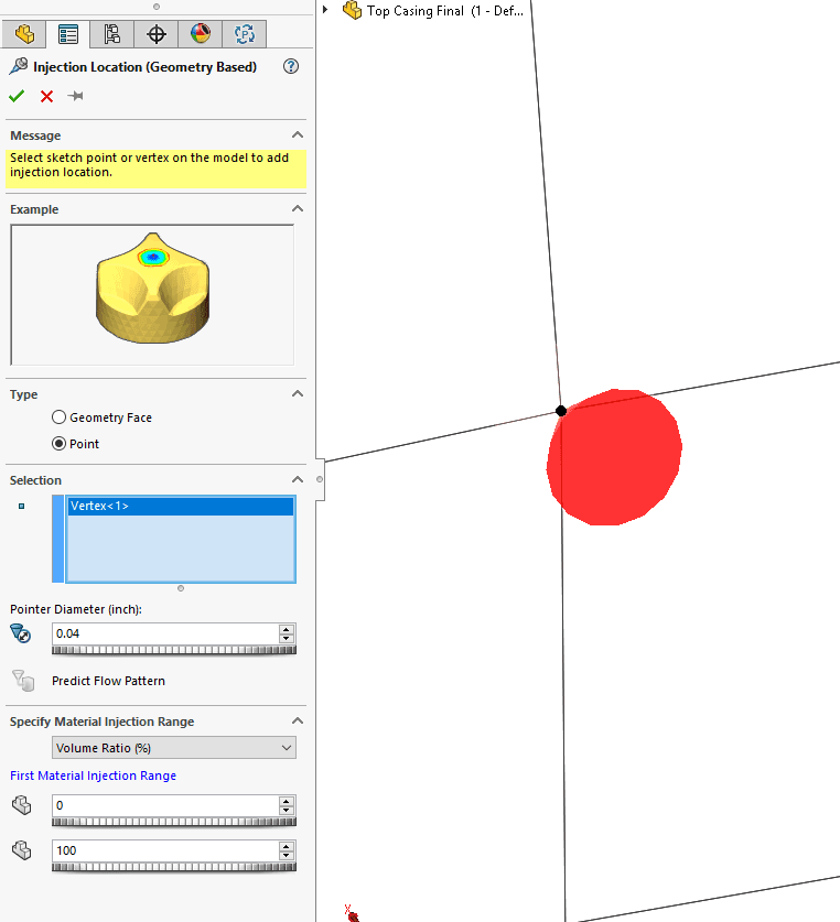
Use of Split lines is suggested for the Geometry Based injection locations if a location is required other than the center of a face. Application to vertices allows you to specify the split line location or a vertex of the geometry.
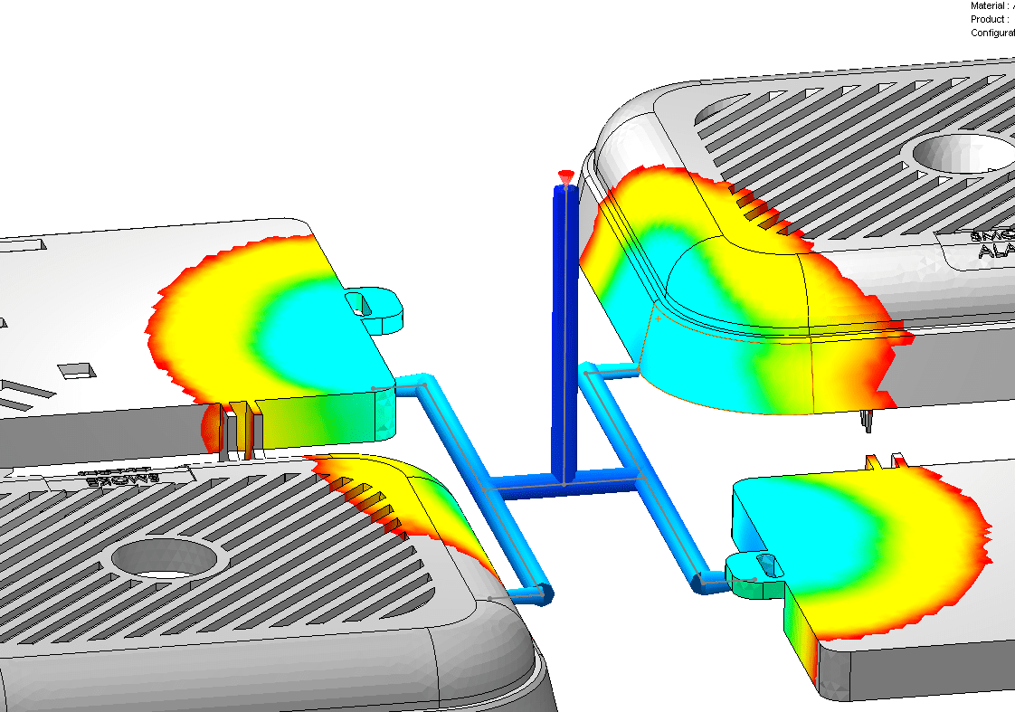
For a virtual runner system, both the Mesh Dependent and Geometry Based injection locations work. The same rules apply for re-meshing and geometry changes.
Having two injection location types adds boundary condition flexibility to SOLIDWORKS Plastics Simulation. For more information please reach out to CATI, and don’t forget to check out other CATI blogs.

Robert Warren
Simulation Specialist, Elite Application Engineer
Dad, Husband, Mechanical Engineer, Jeep and Sasquatch Aficionado
Computer Aided Technology, LLC