3D Interconnect & SOLIDWORKS CAM: A Powerful Combination
Importing files. Nobody likes it – something can always go wrong, and frequently in the best of cases you’re left with a “dumb solid” with no sketches, drawings, or anything. In SOLIDWORKS 2017, Dassault introduced 3D Interconnect – a revolutionary technology which dramatically simplified working with multiple vendors, designers, or freshly acquired subsidiaries.
3D Interconnect is generally touted for use in Assemblies or the creation of derived parts without losing any of the original files’ data, metadata, or fidelity. There is, however, another application which my fellow CNC machine programmers will appreciate: SOLIDWORKS CAM works seamlessly with 3D Interconnect.
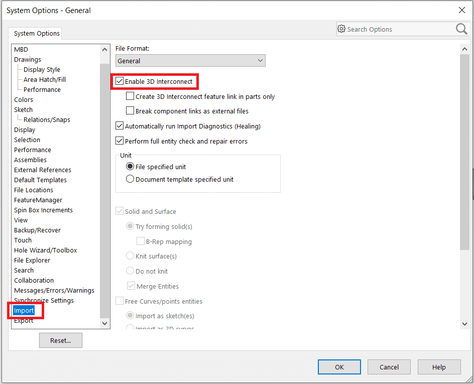
The first step is to ensure that 3D Interconnect is enabled. This can be accomplished by clicking the gear icon in your taskbar or using Tools > Options…
Navigate to the “Import” section in “System Settings” to enable 3D Interconnect as shown in the image below:
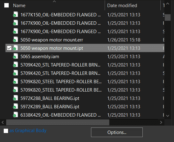
Next, we’re going to import an Inventor part file made by a friend of mine for a combat robot. This part was designed with UHMW plastic in mind:
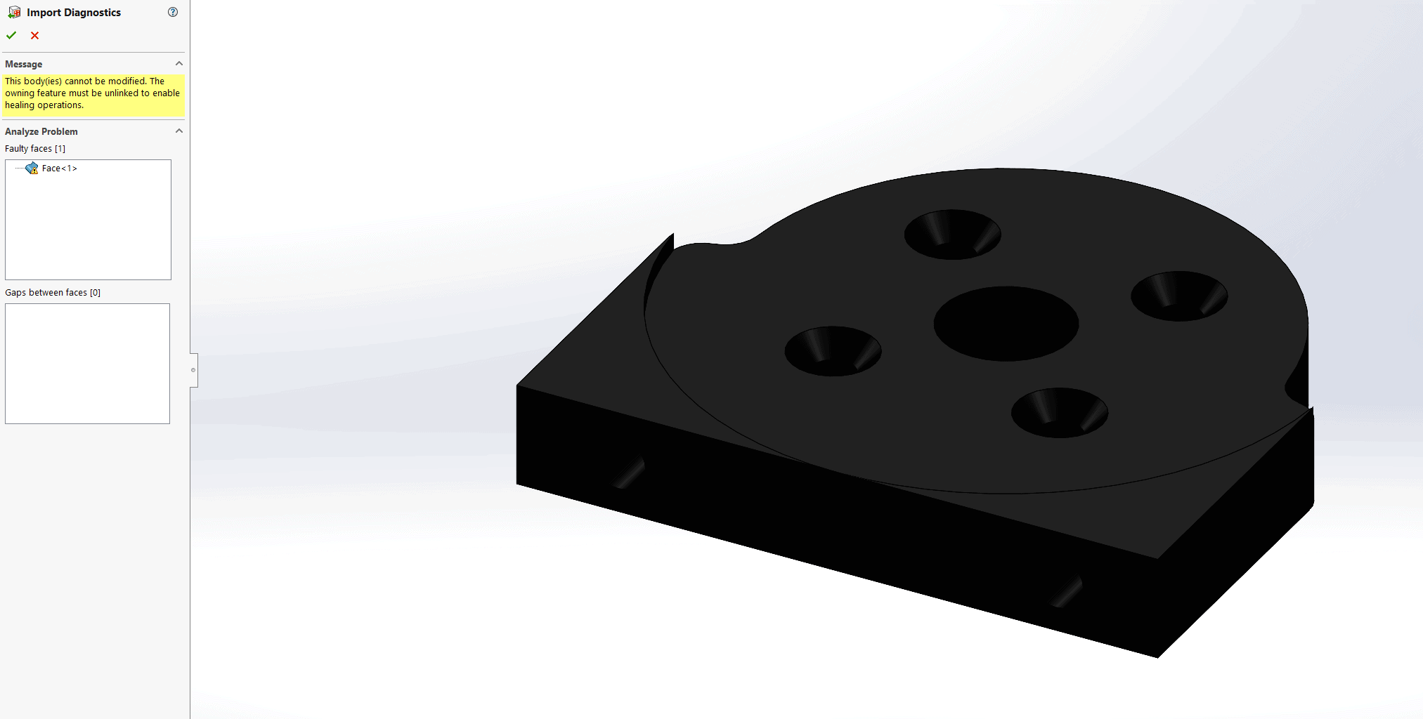
SOLIDWORKS will prompt us for the templates to use and you may run Import Diagnostics if you wish. To speak to the power of this combination, however, I will point out that this particular part has errors I will leave unresolved:
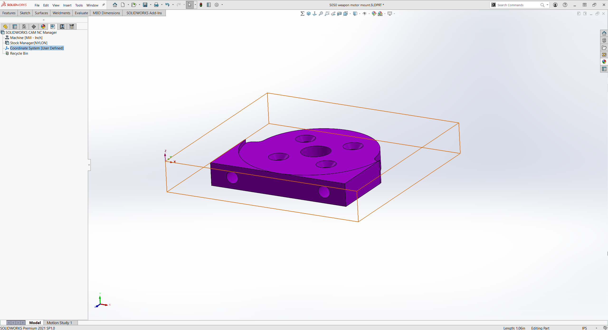
To improve visibility, I will be changing the color of this part and the display style to “Shaded with Edges.”
From here, I can simply proceed as I would with any standard SOLIDWORKS CAM setup – I will define my machine, post processor, stock, and coordinate system.
Does the one-eyed, one-horned, flying, purple people eater eat one-eyed, one-horned, flying, purple people, or is it a one-horned, flying, purple creature which eats people?
I have previously indicated that this part was designed for UHMW where the stock material selection is nylon. My Technology Database does not have UHMW in it, but nylon is a close start and I will be able to adjust that material setting later (stay tuned for adding materials to your TechDB!).
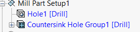
When recognizing features for my first part setup (on the “top” of the part as shown above), it does not fully capture what needs to be done, however the bulk of the work is captured – a boring operation and a group of countersunk drills:
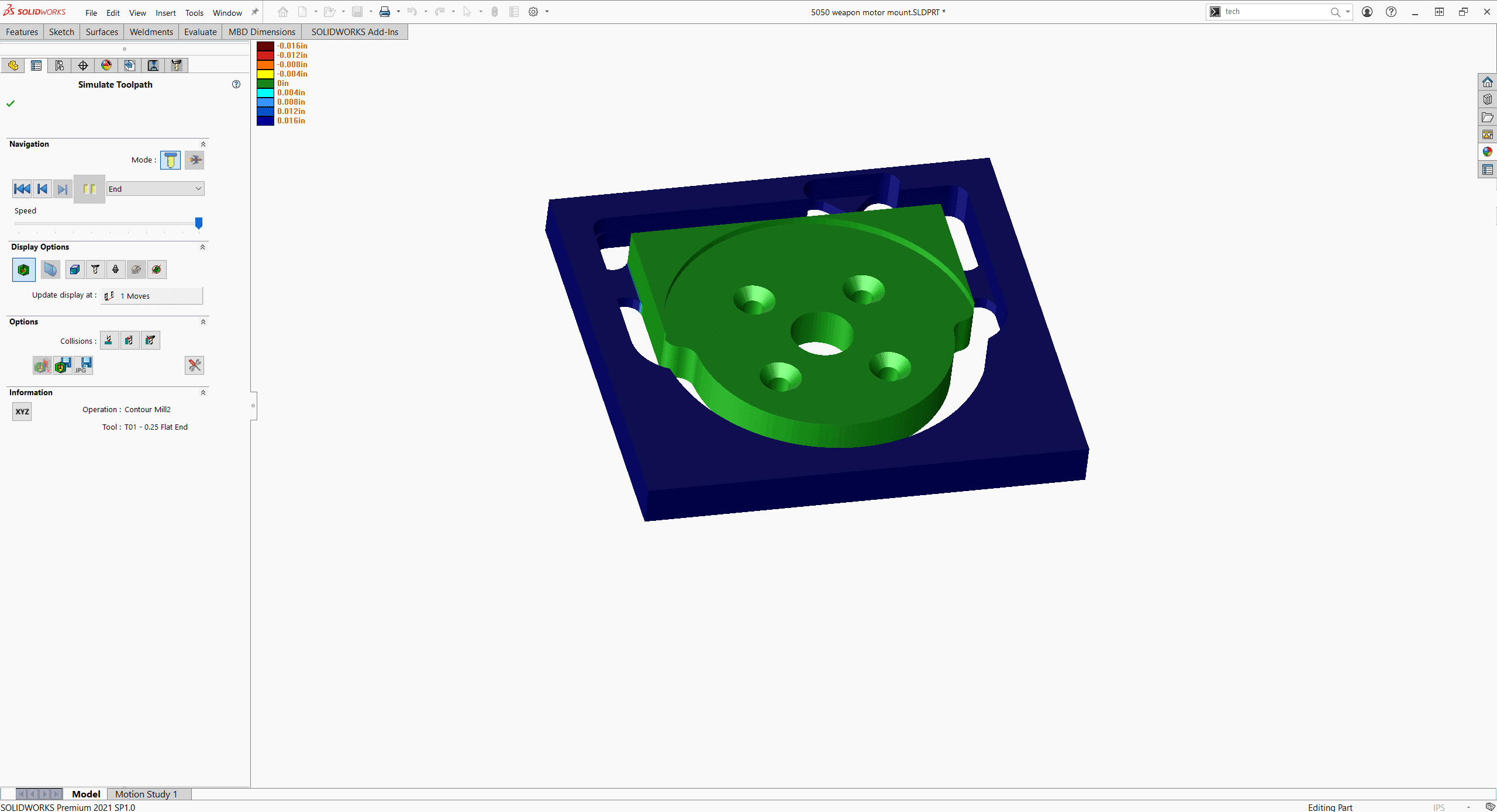
By selecting faces and adding 2.5D operations, however, we are able to quickly add a face, open pocket, and part perimeter features, and in under ten minutes we have gone from an Inventor part file to posting G-Code out of SOLIDWORKS CAM:
Mike Thompson
SOLIDWORKS Application Engineer – CSWP
Computer Aided Technology, Inc.