How many ways can I simplify an analysis in SOLIDWORKS Simulation?
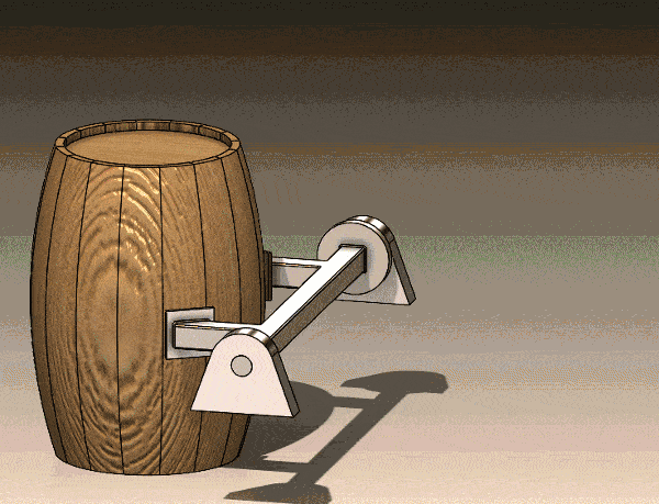
Imagine the following machine design scenario. I am tasked with generating early validation data for a machine that flips barrels from one conveyor to another. The barrel is constructed of American Oak wood staves that are charred, then filled with liquid that will be stored for a very long time. Years, in fact, if done correctly! The machine will flip the barrel from one side to the other in three seconds. Finally, the mass of the barrel and contents are approximately 236 kilograms, or 520 pounds.
Animation of Barrel Lifting Mechanism
For my initial structural validation, the mechanism to grasp the barrel sides is not yet known. These are identified by the red boxed regions (Figure 1). There will be an appropriately sized motor connected to the main shaft of the lifting/flipping mechanism at one end, designated by the orange arrow (Figure 1). While this process will be repeated tens of thousands of times, my initial task is to determine if the current design can withstand the gravitational and centrifugal loading. Also, even though liquid sloshing inside the barrel will occur, that will be ignored for preliminary analysis work. With the requirements understood, let’s review several methods of approaching this problem with SOLIDWORKS Simulation.
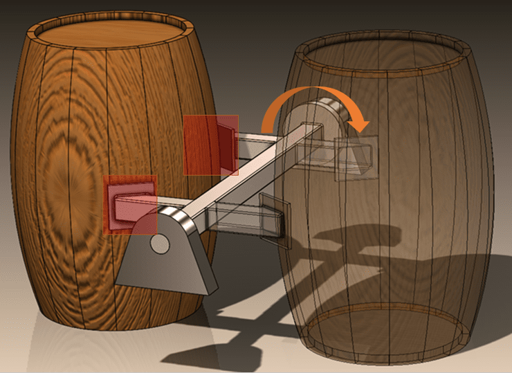
Figure 1. Barrel lifting/flipping machine
The first Linear Static study is set up with only the barrel and the lifting structure of the machine. In Figure 2, fixed hinge restraints (A) at each end represent pillow block bearings to support the lifting structure. An On Cylindrical Face restraint (B), preventing circumferential motion represents the motor holding the mechanism at the starting position. Since the barrel grasping mechanisms are unknown, the barrel will be “attached” to the mounting plates using Rigid Connectors (C). Gravity is the only load included in this first analysis. Due to the disparity in size of components, a mesh control had to be applied to the lifting structure body for a mesh to be created.
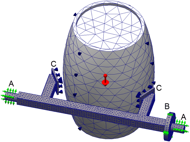
Figure 2. First finite element model details and mesh
The results of my first analysis using rigid connectors and only a gravitational load is shown in Figure 3. The maximum Von Mises Stress is 47.77 MPa. The lifting mechanism is constructed with Cast Alloy Steel having a yield stress of 241 MPa. The calculated Factor of Safety for this analysis is 5.1. The maximum displacement result might also be an important quantity to verify, it is 0.362 mm. I have edited the Advanced Options definition of the result plots to show only the lifting structure for this study.
Figure 3. Study 1 results, rigid connector and gravity
While using rigid connectors to represent the barrel grasping mechanism is a nice simplification, including the barrel increased the mesh size and initially caused problems without an added mesh control. The second simplification is to use a remote mass to represent the barrel (Figure 4). This removes the rigid connector boundary conditions from the setup. This also removes the barrel from the finite element mesh, which reduces the size of the problem to be solved.
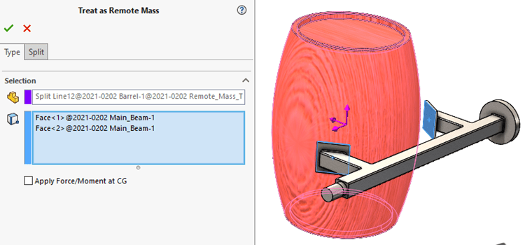
Figure 4. Remote mass setup
After meshing the lifting mechanism with a similar mesh size as the first study and solving the analysis, I need to compare the stress and displacement results to the first finite element model. The second study (remote mass, only gravity) has a maximum Von Mises stress of 47.54 MPa and a maximum resultant displacement of 0.362 mm (Figure 5). Using a remote mass for the barrel led to a maximum stress that is 0.23 MPa (0.4%) lower than the first study while maximum displacement is unchanged. This result gives me confidence that future finite element studies of this mechanism can use the remote mass option instead of including the barrel. Well, at least I know that using a remote mass with only a gravitational load is acceptable.
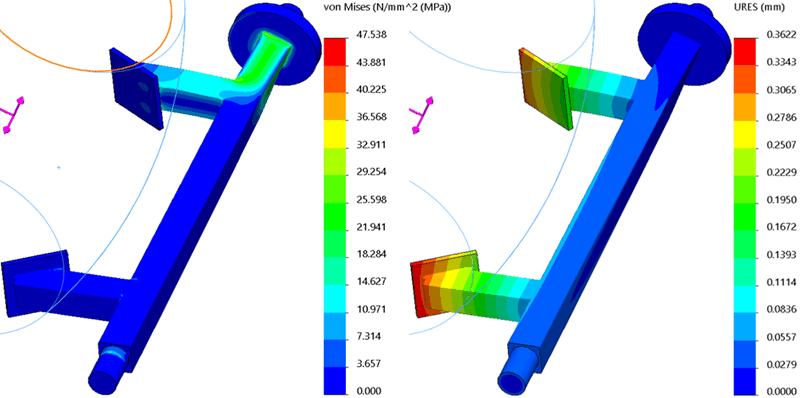
Figure 5. Study 2 results, remote mass and gravity
I am going to revisit the first study setup with the rigid connectors between the lifting mechanism and barrel. That study only included a gravitational load, however, the lifting mechanism will also experience a centrifugal load as the barrel is lifted. I will not go into the details of setting up a SOLIDWORKS Motion study to determine the angular velocity and angular acceleration values, however, the setup of the centrifugal load is shown in Figure 6.
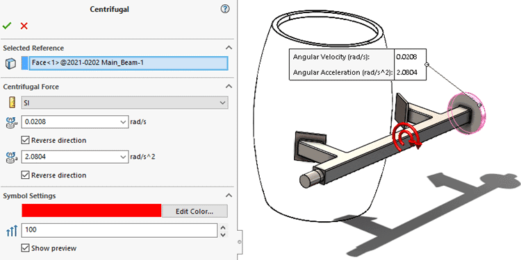
Figure 6. Centrifugal load setup
After adding the centrifugal load to the first study and solving that updated finite element model, the stress and displacement results increased. The maximum Von Mises stress is 54.55 MPa and the maximum displacement is 0.412 mm (Figure 7). The Factor of Safety is now 4.4.
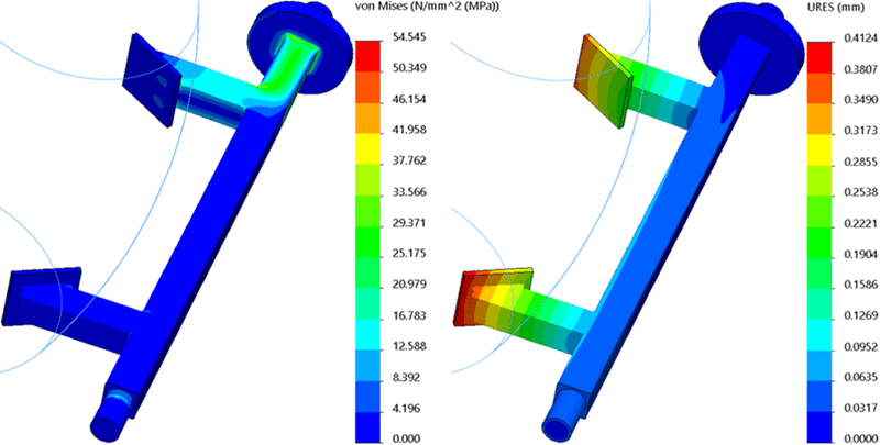
Figure 7. Study 3 results, rigid connectors with gravity and centrifugal load
Just as I had done with the second finite element study, I will replace the rigid connectors and barrel with a remote mass. For this fourth study I will also include the centrifugal load boundary condition. In performing this step, I am re-visiting my verification that the remote mass was an acceptable simplification with the addition of a centrifugal load.
The results of the fourth analysis are shown in Figure 8. The maximum Von Mises stress is 54.27 MPa and the maximum displacement is 0.412 mm. This is a 0.28 MPa (0.5%) reduction in maximum stress while the displacement is again unchanged, validating that utilizing a remote mass is an acceptable simplification with centrifugal loading.

Figure 8. Study 4 results, remote mass with gravity and centrifugal load
There is one last simplification I need to investigate. The previous examples were all possible because I had the geometry and mass properties of the barrel to include in the SOLIDWORKS assembly. What if I had been brought into the design process even earlier, before the geometry of the barrel was finalized? Let’s assume that the only information I am provided about the barrel is its’ center of gravity and mass. Is this enough information to set up and solve a final finite element model of the lifting structure?
The fifth finite element model uses a Remote Load/Mass to represent the unfinished barrel design. To make the finite element model setup a little easier, I created a reference coordinate system in the assembly where the CG of the barrel will be at the start of the lifting process. Then, in the finite element model setup, I will reference the CG and assign the mass to be attached to the connection locations of the lifting structure (Figure 9).
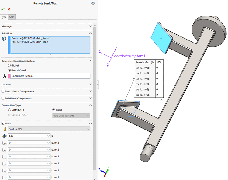
Figure 9. Remote Loads/Mass setup
After meshing and solving this study, I want to compare how this simplification compares to the third study (rigid connectors, gravity, and centrifugal loads). The results of this fifth analysis are shown in Figure 10. The maximum Von Mises stress is 52.33 MPa and the maximum displacement is 0.398 mm. These values are 2.22 MPa (4.07%) and 0.014 mm (3.40%) less than the third study results. The Factor of Safety for this fifth finite element model is 4.6. I think you would agree that this relatively small difference in results is acceptable, given the only information about the barrel in the analysis is its’ CG and mass.
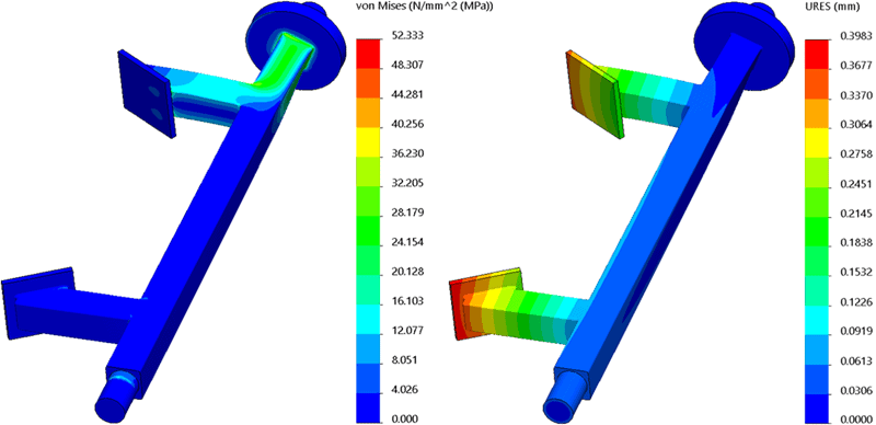
Figure 10. Study 5 results, Remote Loads/Mass with gravity and centrifugal load
Did you count how many ways was I able to simplify the analysis? If you only counted the rigid connectors, remote mass, and remote loads/mass, you missed a few. The fixtures representing the pillow block bearings and the on cylindrical face restraint are also simplifications of real geometry. Neither of these boundary conditions account for the flexibility of the bodies they represent. The same can be said for neglecting liquid sloshing inside the barrel, which would increase the complexity of the loading. Each of these simplifications, or assumptions, are necessary to create a simplified finite element model that I can easily mesh and quickly solve. Also, since the Factor of Safety is well above 2, I can begin to investigate design changes to reduce material use or evaluate the service life of the mechanism by solving a Fatigue analysis. What next steps would you take? Now go make your products better with SOLIDWORKS Simulation!
Bill Reuss
Product Specialist, Simulation
Father, Golf Junkie, Coffee Connoisseur, Computer Nerd
Computer Aided Technology, Inc.