SOLIDWORKS Flow Simulation Meshing – Global Manual Settings: Part 1
This blog continues the quest to understand the computational fluid dynamics (CFD) mesh settings in SOLIDWORKS Flow Simulation that I initiated in my first blog. The focus there was on the global automatic settings. Here, I dive into some of the manual settings, which offer multiple ways to influence the size and arrangement of cells. As stated previously, the goal is to create an accurate mesh without an excessive cell count that will allow an efficient and accurate solution.
“In a previous episode…”
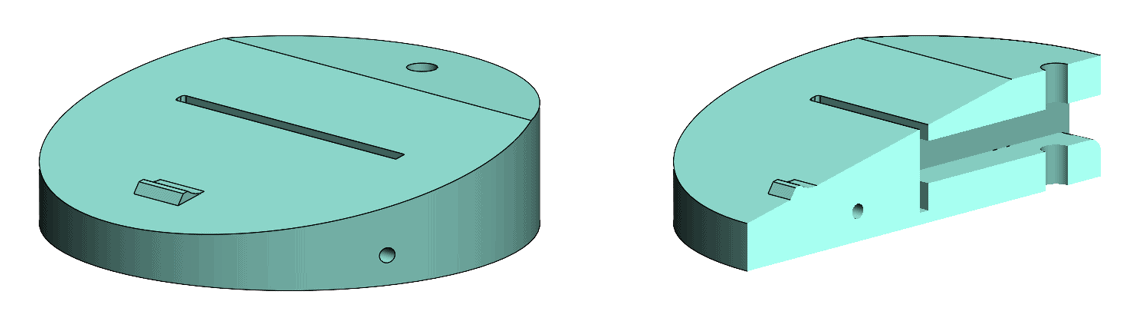
The geometry I introduced in the first blog shown below contains narrow passageways, drilled holes and a small bump feature on the top angled surface.
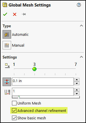
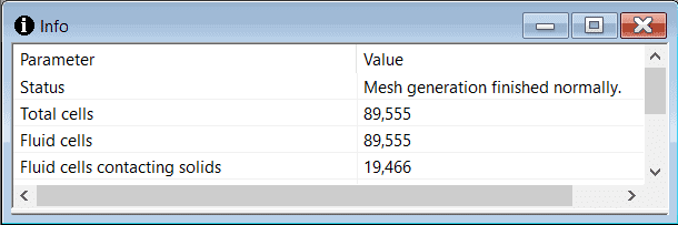
Here’s where I left things in that blog. Using the global automatic settings with a minimum gap size of 0.1 in. and “Advanced channel refinement” resulted in creating 89,555 fluid cells, 19,466 contacting solids, with the small passageways adequately resolved.
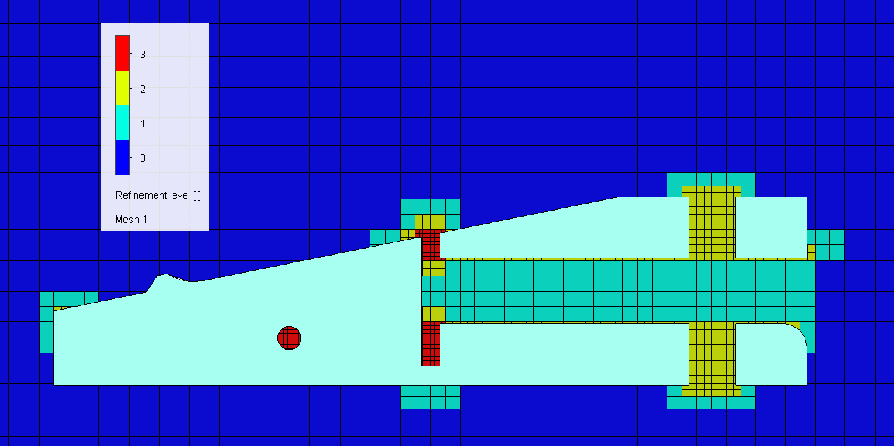
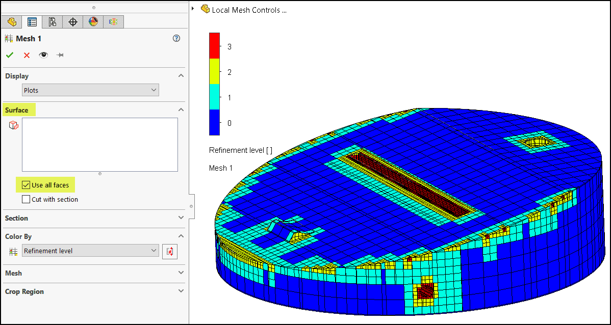
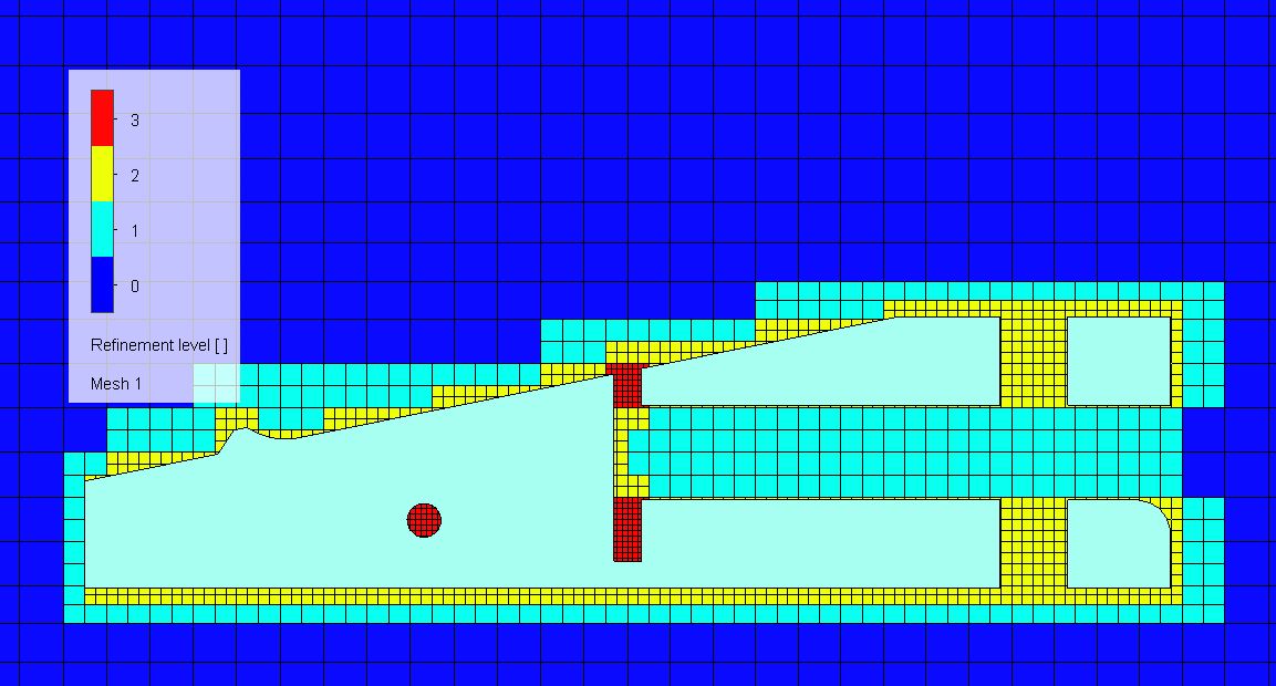
But what about the outside profile of the part and the small bump on the angled surface? How well have these been resolved by the mesh? From this plot it appears that those areas need further refinement.
Taking another look…
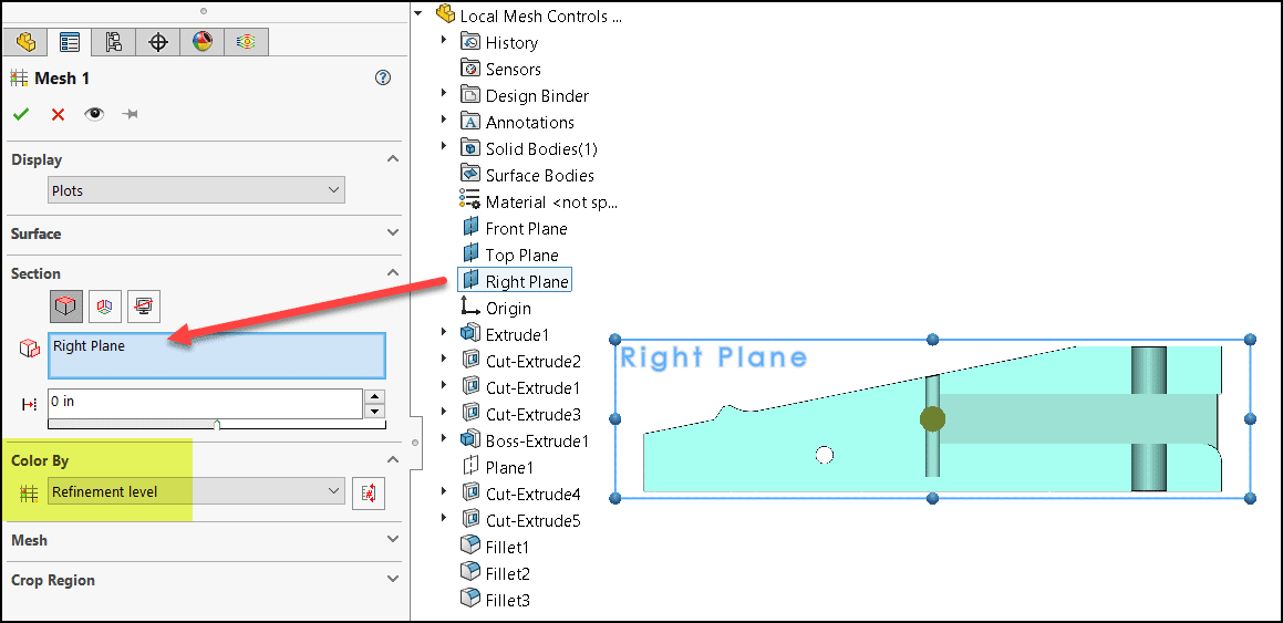
Note that the mesh can be displayed on any cut plot in SOLIDWORKS Flow Simulation. The plot above is a dedicated mesh-only plot, with color-coding of the refinement level. This is important information to have when designing the mesh in a Flow Simulation project. Here’s a look at the settings I used to create this plot.
To insert a mesh plot:

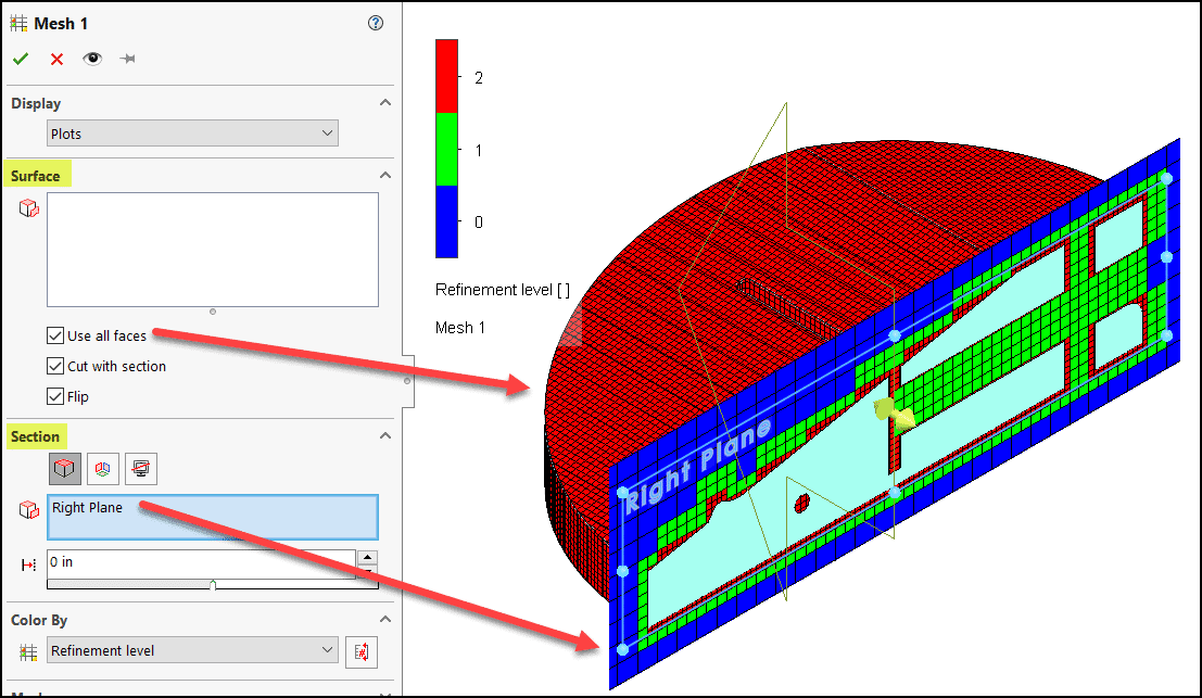
The settings used for the plot:
To see how the edges and surface features of the part were meshed, switch to the “Surface” option in the property manager and use the “All faces” option:
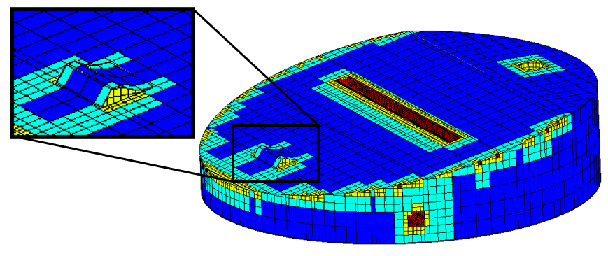
As with CAD, seeing things in 3D unlocks some very important information! Not all of the corners have refined cells, nor has the small bump been completely resolved.
Now, the new stuff – global manual settings!
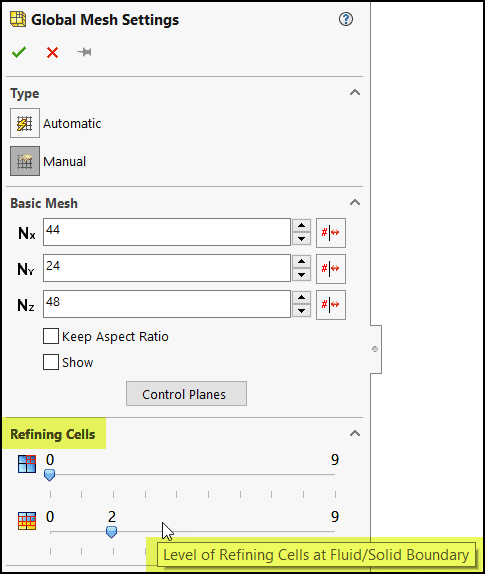
While this might be an adequate mesh for initial results, I’ll show how the global manual settings can be used to significantly improve the mesh without adding a ton of additional cells. First up, after picking the manual type, is the “Refining Cells” section of the Global Mesh Settings property manager, as shown below. Since I’m interested in capturing the solid features better, the second slider in this section can be used to influence the cells at the fluid/solid boundary (the first slider affects the fluid cells.)
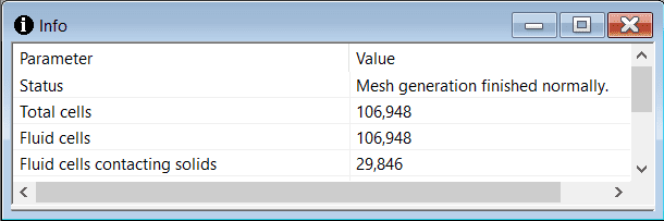
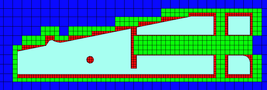
Forcing a Level 2 refinement for the boundary cells produced the mesh shown below with 106,948 fluid cells and 29,846 contacting the solids. (Note the combined use of “surface” and “section” settings in the plot.) I used the “crop region” to cut away some of the section plot for better visibility of the part faces behind it, which have been completely captured with level 2 refined cells!
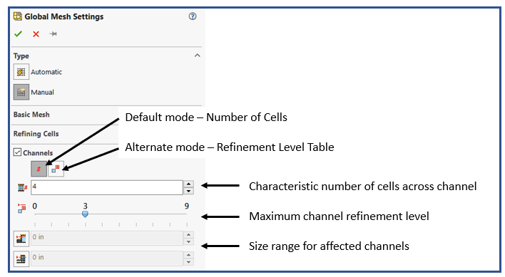
While the small passageways were resolved, improvements should be made to put a couple of additional cells in those areas. To do so, look no further than the “Channels” section of the property manager! This option turns on functionality similar to the automatic “Advanced Channel Refinement” that I showed in the previous blog. (In switching to Manual mode the automatic controls used previously no longer have an effect on the mesh.) Here, there are two modes to choose from; I’ll address the default mode, which allows setting the desired number of cells. As shown below, there are two controls, the “Characteristic number of cells across channel” and a slider for the “Maximum channel refinement level”, with the ability to limit which channels these controls apply to based on a range of channel widths.
With these settings the following mesh was created with 134,976 fluid cells, 40,054 contacting solids.
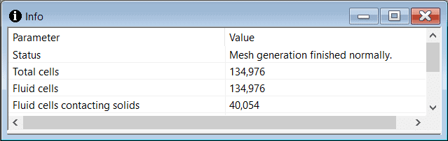
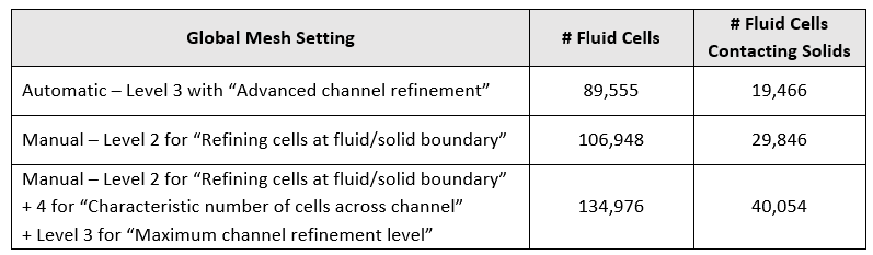
This mesh has captured both external features and internal passageways well and is a great starting point for an external flow analysis. Here’s a summary table showing how the cell count grew with successive applications of the mesh settings discussed in this blog. The total cell count is very reasonable for the final mesh.
I hope this blog on the subject of CFD meshing with global manual settings has increased your confidence and will allow you to create more efficient projects in SOLIDWORKS Flow Simulation. Watch our blog page for more to come on this subject. Please experiment with some simple geometry, as I have done, to apply what you’ve learned here. I’m confident you will immediately begin to improve your projects!
Kurt Kurtin
Sr. Product Manager, Simulation
Computer Aided Technology, Inc.