Give Cyclic Symmetry a Spin in SOLIDWORKS Simulation
If I told you that it was possible to make your analysis solve faster, would you be interested? You absolutely should be! Faster solve times allow you to analyze more iterations and make better informed decisions to improve your designs. Today I am going to explain how to use another method of reducing your finite element model using Cyclic Symmetry in SOLIDWORKS Simulation.
Hopefully you are familiar with using a symmetry boundary condition in SOLIDWORKS Simulation. Symmetry allows you to analyze a portion of the full geometry, usually a half or a quarter of the whole. For a symmetry restraint to be valid, the geometry, restraints, loads, and material properties also need to be symmetric. When using symmetry, the nodes on the cut face of the finite element model are restricted to move only on the cut plane, not normal to the cut face. A simple way to think about this is to consider what would happen if you kept the geometry on the opposite side of the cut plane. If a node could move normal to the cut face, that would imply that the opposite side would also move normal, either creating an interference within the body to itself or a void in the geometry. That, of course, does not happen.
What if your finite element model includes boundary conditions that would cause nodes on the cut plane face to move in the normal direction? Unfortunately, you can no longer use the symmetry restraint. That does not automatically mean you cannot reduce the size of the finite element model! You just need to review the boundary conditions and ask a new question – are the boundary conditions rotationally symmetric? In SOLIDWORKS CAD terms, could I make a circular pattern of these finite element model features? If the answer is yes, then you should consider using Cyclic Symmetry to reduce the size of the problem.
To demonstrate cyclic symmetry, I will use a v-belt pulley (Figure 1). The fixtures used are a roller slider to prevent axial translation, a fixed hinge on the center diameter, and also fixed hinge restraints to represent the bolted connections. The loads transmitted to the pulley from the v-belt will be represented by a torque and a radial force acting towards the center of rotation. While the forces acting on the pulley are intermittent during use, I will assume these loads are always acting on the v-belt to pulley contacting faces.
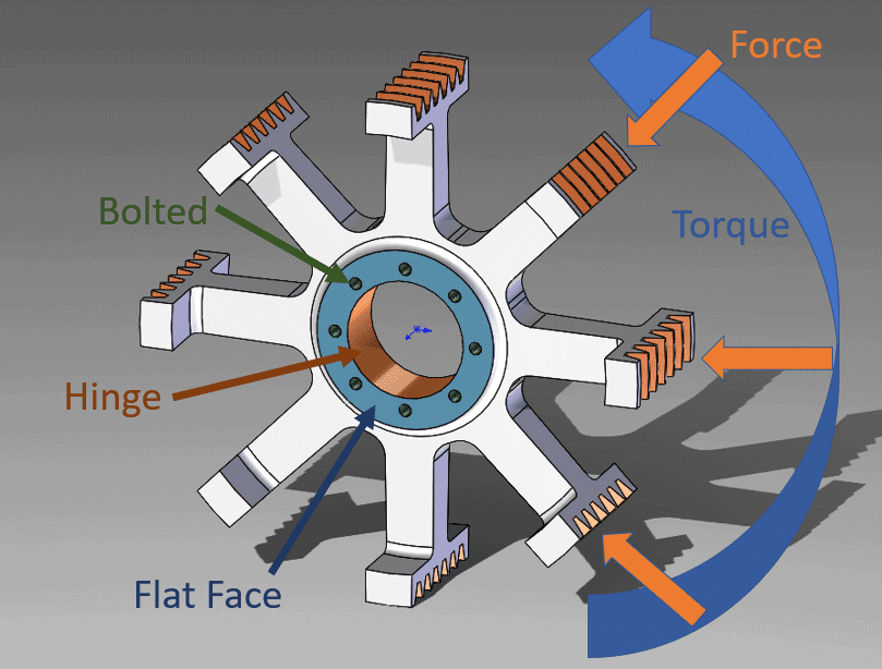
Figure 1.
Using the standard meshing algorithm, default mesh size, and high quality elements for the full model, there are 25,545 nodes and 14,265 elements. After solving the SOLIDWORKS Simulation study, the calculated maximum Von Mises stress is 34.0 MPa while the maximum resultant displacement is 0.0074 mm (Figure 2).
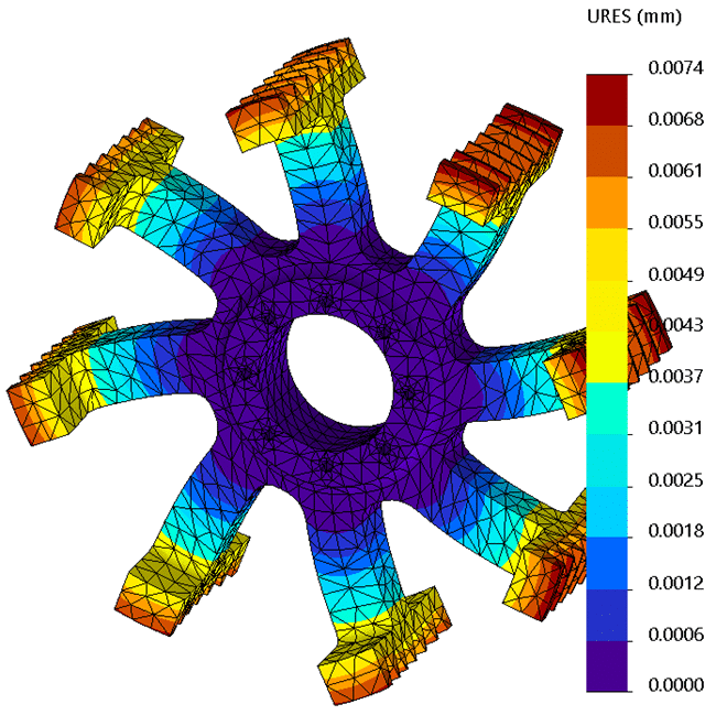
Figure 2.
At this point, let’s assume that I do not know about cyclic symmetry for a quarter-symmetric model. Creating a new finite element study with one quarter of the geometry, I will still use the fixed hinge restraints and the roller/slider restraint, but the loads will be reduced by 75%. I will (incorrectly) add symmetry restraints to the two cut faces of the CAD model. If I mesh this quarter-symmetric model with the standard meshing algorithm, high quality elements, and the same element size from the full model, there are 7,402 nodes and 3,731 elements. After solving this study, the maximum Von Mises stress is calculated to be 31.9 MPa with a maximum resultant displacement of 0.0067 mm (Figure 3).
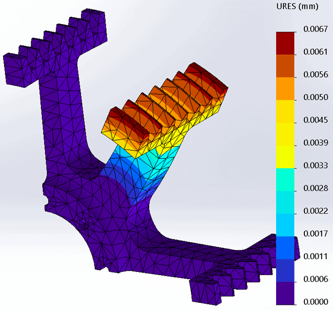
Figure 3.
While the magnitude of results did not change significantly, it should be apparent from Figure 3 that the results are not equivalent. This is the result of an incorrectly applied restraint. Since the nodes on the cut faces are not permitted to move normal to the cut plane, the added stiffness (from the restraint) changes their response.
The restraints on the cut faces should have been cyclic symmetry, not normal symmetry. A cyclic symmetry restraint requires a reference axis, the cut faces should be similar in shape, and the cut section must be capable of being patterned evenly divisible by 360 degrees. The setup of a cyclic symmetry restraint requires selecting the opposing face pairs and the reference axis (Figure 4).
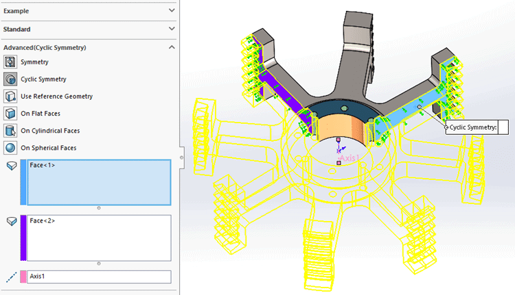
Figure 4.
After re-meshing this study with the standard meshing algorithm, high quality elements, and the same size as the full model, the total number of nodes is 7,042 with 3,731 elements, the same as before with the normal symmetry restraint. The maximum Von Mises Stress is calculated to be 32.4 MPa with a maximum resultant displacement of 0.007 mm (Figure 5). Visually, the results for this quadrant of the model once again match the visual results of the full model.
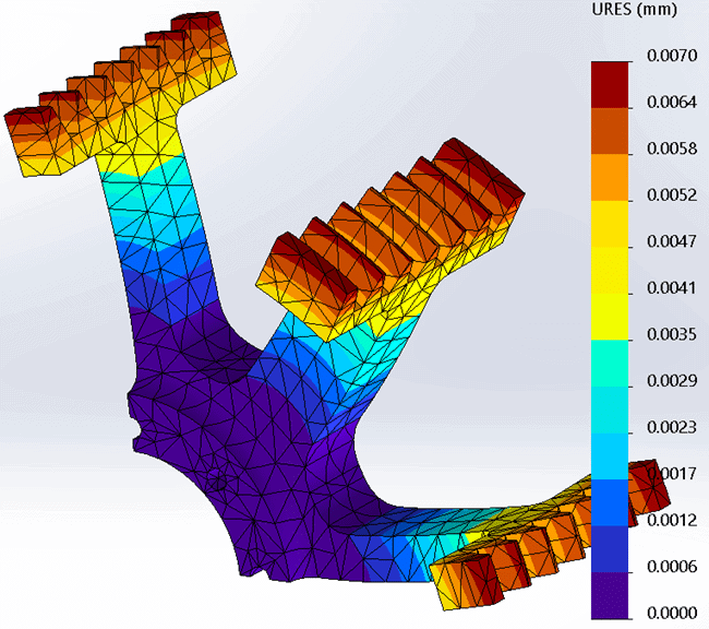
Figure 5.
With cyclic symmetry, I can utilize an even smaller section of the CAD model and have the restraint still be valid. Since the full v-belt pulley has eight equal patterned features to make up the whole, I can create a one-eighth symmetry CAD model and use that in a finite element study. An added benefit is the smaller CAD model can also use a smaller element size. While this will increase the size of the problem, smaller elements generally lead to more accurate results. (For more information regarding the finite element mesh consider reading Take Control of Your Mesh and Divergence and Convergence for Simulation Results.) The 1/8th symmetry finite element model has 13,113 nodes and 8,046 elements. The maximum Von Mises Stress was calculated to be 34.5 MPa with a maximum resultant displacement of 0.0071 mm (Figure 6).

Figure 6.
Using cyclic symmetry for the v-belt pulley allowed me to create a smaller finite element model while still achieving accuracy in the results. The next time you have a model where symmetry can be utilized, be sure to consider if the symmetry constraint is normal symmetry or cyclic symmetry. Incorrect application of a symmetry restraint can lead to incorrect results. After reading this blog, you should understand the difference. Now go make your products better with SOLIDWORKS Simulation!
Bill Reuss
Product Specialist, Simulation
Father, Golf Junkie, Coffee Connoisseur, Computer Nerd
Computer Aided Technology, Inc.