How to use the ruler tool in SOLIDWORKS Flow Simulation!
SOLIDWORKS Flow Simulation is an extremely powerful tool. Studies can be setup quickly and run efficiently and accurately. As a result of its ease of use, customers can iterate and solve a variety of scenarios quicker than if they were performing physical testing. In today’s blog, I will show you a great tip on how to validate the computational domain and understand distances in results via the ruler tool in SOLIDWORKS Flow Simulation!
The computational domain in SOLIDWORKS Flow Simulation is the bounding box that controls how large the fluid domain in a study will be. The larger the domain is, the more fluid cells that will be meshed. With such a variation in the computational domain, it is imperative to have a domain sized appropriately for the physics you are trying to capture, and to solve as quickly and accurately as possible. To size a computational domain, you first need to generate a new study.
In this blog I will be looking at a simplified light pole (Image 1) that sits out in my neighborhood. I want to run a wind study on this pole and thus I will need to run an external flow study. With external studies, it is important to have a large enough computational domain to show wind effects upstream and downstream of the object.
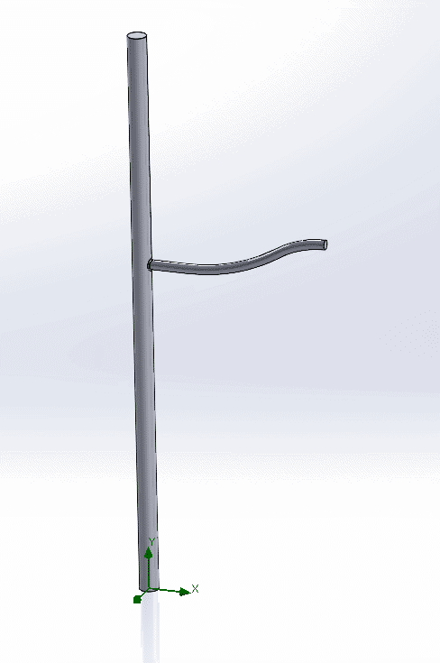
Image 1: Light Pole
After creating the flow simulation study, I can edit the computational domain by right clicking on the computational domain icon and selecting “Edit Definition”. Within the computational domain settings, I can type in my specified distances for the xyz minimums and maximums (Image 2). The challenge is knowing if I have specified the correct distances for the xyz directions, which is where the Ruler tool can aid us in validating the proper computational domain size.
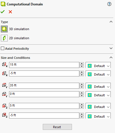
Image 2: Computational Domain Settings
The flow simulation ruler tool will show a grid shaped ruler which will show a scale in the plane you are oriented in. To turn on the flow simulation ruler, go to Tools > Flow Simulation > Results > Display > 2D-Ruler. Note there is also a 3D-Ruler in this same menu, but in our case we want to look at the individual planes so we use the 2D-Ruler. Once we turn on the ruler, a grid will show up in our graphical window that shows us distances. In Image 3, the translucent box represents our computational domain, and the grid shows measurements in the Front Plane which represents our x and y distances. Looking at this grid we can tell we have specified the x and y minimum and maximums for our computational domain correctly, now we need to check the z direction!
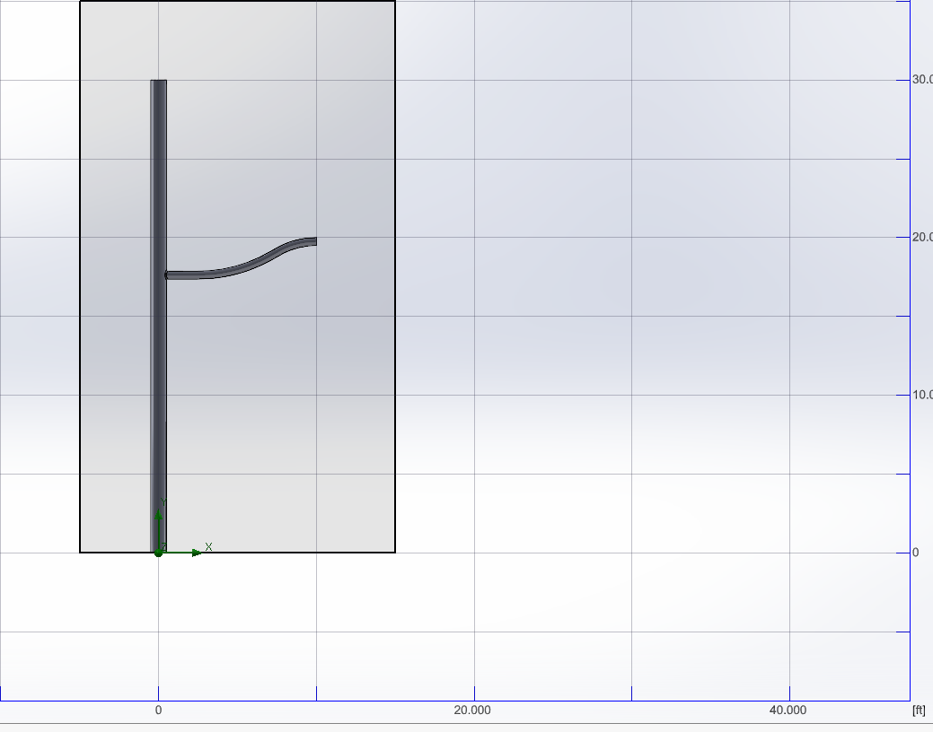
Image 3: 2D Ruler with Computational Domain of Light Pole Front Plane
The beauty of the ruler tool is we can also check our sizes in different planes. We now want to check our z sizes, so if we change to the right plane, we can see our computational domain size in the z and y directions (Image 4). The z directions in the ruler tool indicate a total distance of 10 feet, which matches up with the values we have keyed into our computational domain settings.
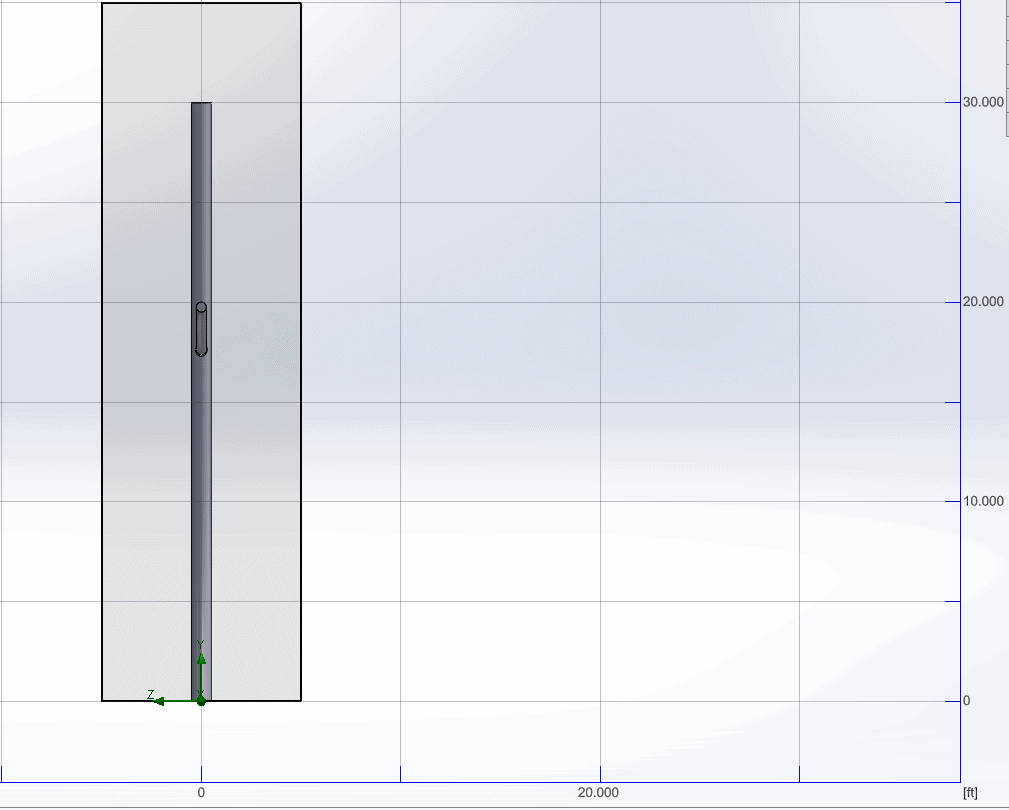
Image 4: 2D Ruler with Computational Domain of Light Pole Right Plane
The last really cool trick of the ruler tool, is it can also be used during post processing flow simulation results. So in our case if we look at a cut plot of our wind study, we can quickly tell where our high and low velocity points are for our light pole. If we were to probe a specific location in our model, we could then use the ruler tool to determine at the exact location that value is occurring at (Image 5).
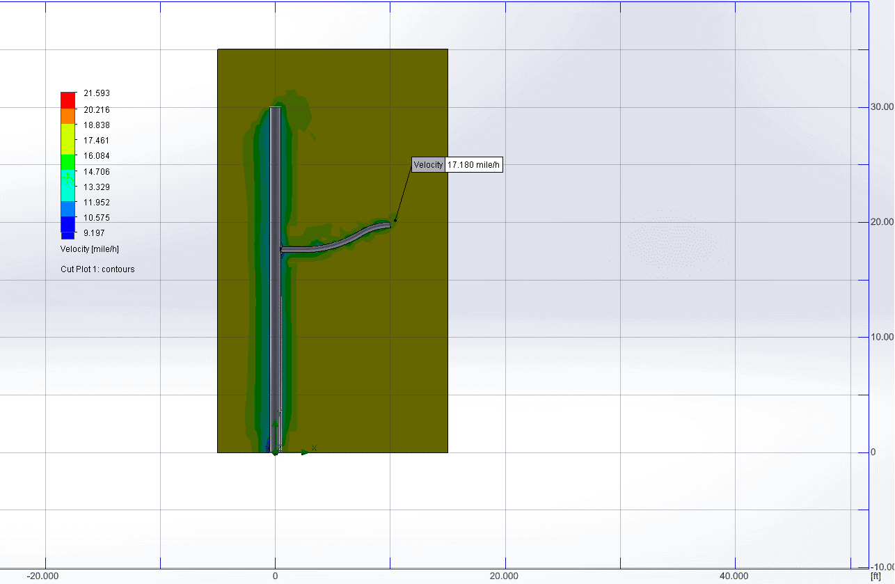
Image 5: 2D Ruler with Cut Plot Results of Velocity
I hope with these tips, you will be able to shorten your validation and postprocessing time in Flow Simulation! If you have any further questions about SOLIDWORKS Flow Simulation, please reach out to us to see how you can utilize simulation to streamline your design processes.
Drew Buchanan
Application Engineer Specialist, Simulation
Computer Aided Technology