SOLIDWORKS Simulation: Statics 101 Using Simulation
Remember back when you took Engineering Statics and you had to find the forces by hand calculations? You may have said to yourself, why do I have to solve all this by hand when we now have simulation software to get the answers we need. Well, that is true that simulation software can be used to get the answers, but how would you use the software to find unknown forces? Hopefully after reading this blog, I will have cleared the smoke of how to solve the forces of a typical Statics problem by hand and how to use SOLIDWORKS Simulation software to prove what you solved mathematically.
An example to consider is shown in Figure 1 below which is a ring subjected to force F1 and F2. If it’s required that the resultant force have a magnitude of 1000 N, how would we determine the magnitude of F1 and F2 by hand and by using SOLIDWORKS Simulation software.
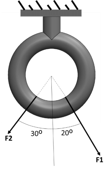
Fig. 1 Ring problem
To start to solve this problem by hand we need to remember vector addition according to the parallelogram law. From there we can use the tip to tail method to make one single vector triangle. See Figure 2 below.
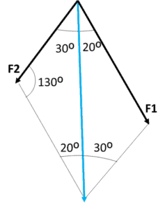
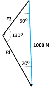
Fig. 2 Vector addition setup
Now that we have a single vector triangle, we can then use the Law of Sines to solve for F1 and F2. See Figure 3 below.


Fig. 3 Solved forces
Now that we know what the force values are mathematically, how do we go about finding these forces in SOLIDWORKS Simulation software? Let’s first start with a design of the ring like the one shown in Figure 1 above. Taking advantage of configurations, I made one ring design using very small circular split faces to mimic point loads like they show in any Engineering Statics book and another ring design using larger split faces to mimic rope pulling at the shown angled values of Config two in Figure 4 below. The rectangular ring baseplate was left out of the design because it was not needed for this analysis.
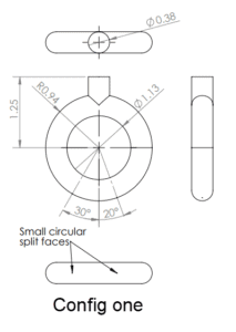
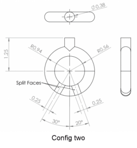
Fig. 4 Ring dimensions
For configuration one the simulation setup is:
- Plain carbon steel is the material type.
- Reference geometry fixtures are applied to split circular faces A and B and using reference planes on the split circular faces. See Figure 5 below.
- A force of 1000 Newtons is applied at the top face of the vertical part of the ring.
- The mesher type used is the curvature based mesher.
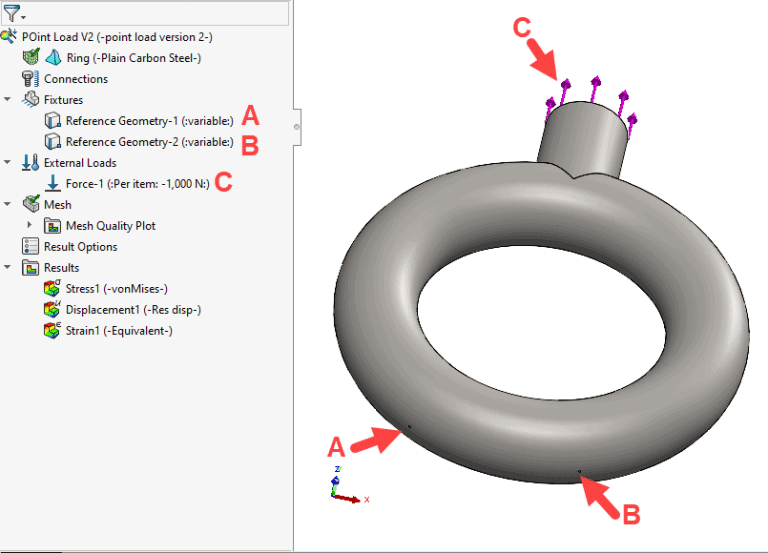
Fig. 5 Config one sim setup
For configuration two the simulation setup is:
- Plain carbon steel is the material type.
- Reference geometry fixtures were applied to the split faces shown at A and B and using reference to the angles sketch lines. See Figure 6 below.
- A force of 1000 Newtons is applied at the top face of the vertical part of the ring.
- The mesher type used is the curvature based mesher.
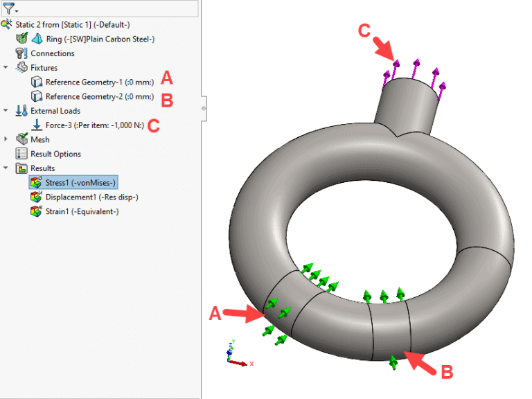
Fig. 6 Config two sim setup
After running the analysis on configuration one and two you can then view the forces in the X, Y, Z, and the resultant force by simply right clicking on the Results folder and choosing List Resultant Force. Notice the resultant force values equate to the force values we found earlier by hand calculations. See Figures 7 through 10 below.
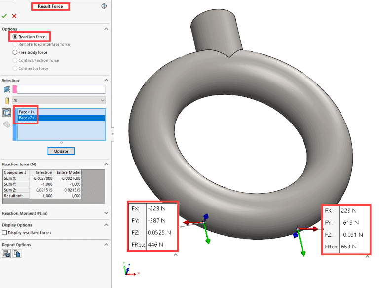
Fig. 7 Config one force values
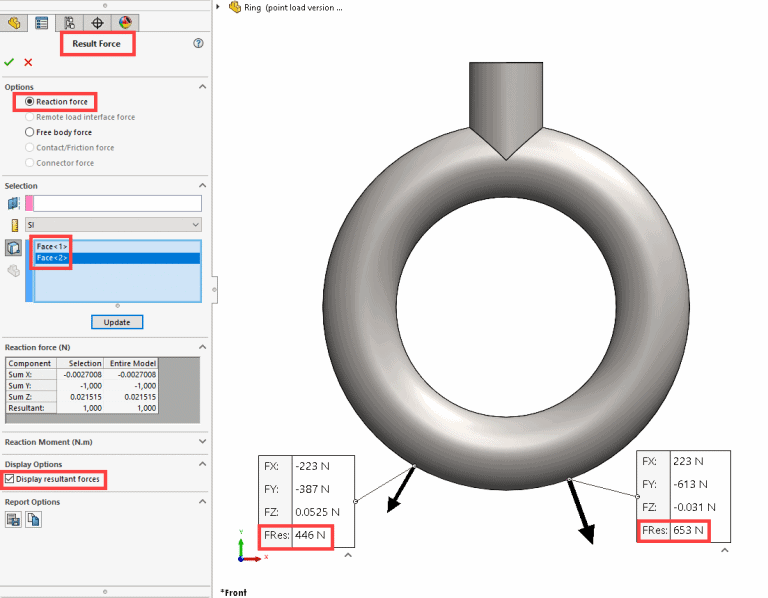
Fig. 8 Config one showing Displaying resultant force arrows only
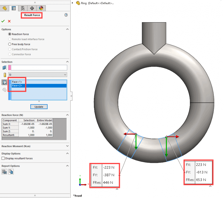
Fig. 9 Config two force values
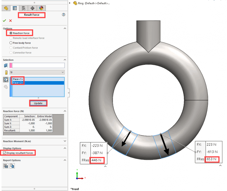
Fig. 10 Config two showing Display resultant force arrows only
In conclusion it turns out that no matter how you slice it, SOLIDWORKS Simulation gives the same values either way. I hope you have found this informative, and I have shed some light about how to correlate hand calculations to SOLIDWORKS Simulation.
Nick Pusateri
Senior Application Engineer Specialist, Simulation
Computer Aided Technology