Can SOLIDWORKS Simulation help my driver shaft find its spine?
All things considered; I would rather be playing golf. I have played in temperatures hovering near 110 Fahrenheit in the shade, when it was snowing, in tornado warnings, and in monsoons. To non-golfers, this is often viewed as a form of psychosis. To golfers, it is par for the course! These days I do not get to play as much golf as I would like, but that does not stop me from planning my next round. It also does not stop me from trying to find an edge, a little performance boost, with off-the-course work. Here is a recent edge that I hope shows on-course gains by using technology. I am going to make my driver shaft use its spine. Even better, I can use SOLIDWORKS Simulation Premium to explain what it is and how it works.
The reality of all manufacturing processes is they are never perfect. Our designs must account for variations in component size, material, processing conditions, assembly procedures, and many other small influences that affect the finished goods. Golf shafts are no different. These slight variations lead to golf shafts tending to flex better, with less twist, along some load orientations than others. In golf terms, this is the shaft having a “spine”. In Engineering terms, we are looking at the bending properties of the golf shaft. Let’s look at what this means and work through an example using SOLIDWORKS Simulation.
The mechanics of what is happening is explained by Beam Theory. Consider the three examples shown in Figure 1. If I took a cross-section of the golf shaft it would look like an annular ring. Version (A) is a perfectly concentric, uniform shaft cross-section with constant material properties. Version (B) is a perfectly concentric shaft cross-section with different material properties, E1 and E2, on the left and right side of the vertical centerline. Version (C) is a concentric circular cross-section with a small, localized thickness variation causing slightly different material properties, E’, at this thickened region.
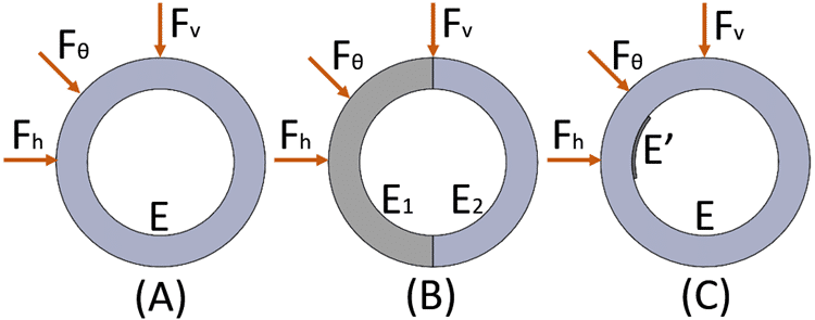
Figure 1
For shaft (A), the bending will be consistent regardless of the load orientation – horizontal, vertical, or at some angle – with respect to the center of the shaft. For shaft (B), the bending will not be consistent from one load orientation to another, with the shaft tending to twist under the applied vertical and off-angle loading. For shaft (C), the bending will only be consistent and have zero twist if the load is applied along an axis passing through the centroid of the shaft aligned with the least moment of inertia of the shaft. For shaft (C), this would require the orientation of the load to be applied somewhere between the horizontal, Fh, and off-angle, Fθ, loading shown in the Figure 1.
I re-created my golf shaft using SOLIDWORKS CAD, published dimensions for the raw stock shaft, but cut to the playing length I use of 46 inches. Since the CAD model is perfect, I intentionally added variations, or slight thickness imperfections on the inside diameter, to the golf shaft model to illustrate shaft spine. With my CAD model complete, in SOLIDWORKS Simulation Premium, I set up a Linear Dynamic, Modal Time History study. I applied a fixed restraint to the grip end of the shaft and a time-based force on the tip-end of the shaft (Figure 2). This simple setup mimics the manual spining process of my driver shaft.
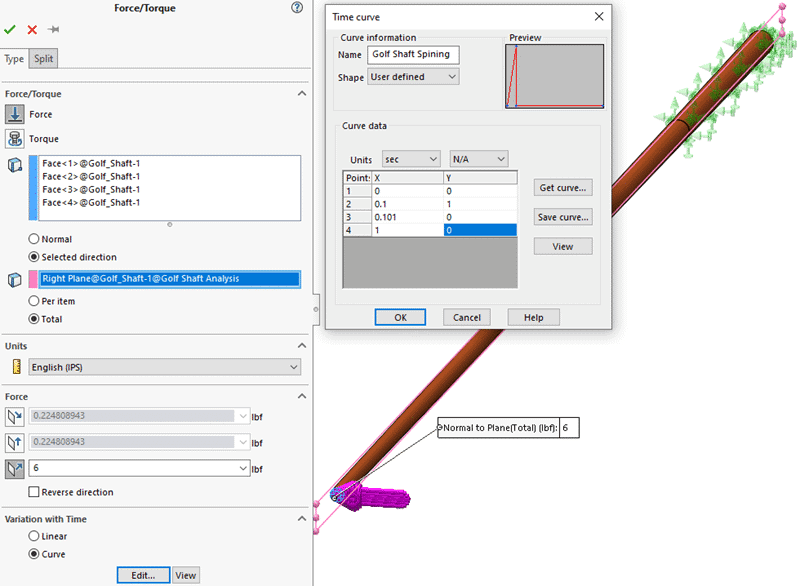
Figure 2
I also set up sensors to track the horizontal and vertical (x and y) displacement of a reference point on the centroid of the golf shaft tip. I solved the first finite element model for the ‘unspined’ shaft and gathered the sensor output. I then modified the orientation of the shaft, re-applied the time-based loading condition, re-solved the analysis, and gathered the second set of data for the shaft tip. The difference in tip displacement between the unspined and spined shaft can be seen in Figure 3.
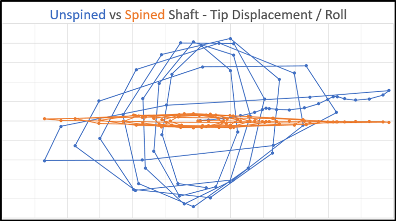
Figure 3
This difference in tip response from the two finite element models is easy to visualize with the above plot. After reading everything prior to this, I hope you are now questioning why the golf shaft spine matters. Simply put, bending of the golf shaft occurs at every stage of a golf swing – from takeaway, to backswing, then transition, into downswing, at impact, and follow-through. To give yourself the best chance at the club head meeting the ball consistently at impact, you want the golf shaft to bend in alignment with your swing plane. Now that you’ve read what shaft spine is, and how it can be analyzed using SOLIDWORKS Simulation Premium, let’s see the spining process in action!
Here are two videos that I took of the golf shaft spining process. My good friend, Joe M., has the equipment in his golf workshop to “spine” golf shafts. This first video shows how the golf shaft will “roll” when the applied load is not oriented with the spine of the shaft.
This second video shows the shaft being re-oriented such that the applied load is aligned with the spine of the golf shaft. The horizontal line drawn by the laser pointer is ideal.
Does the golf shaft spine make a difference? The answer to that depends on how skilled the golfer is. For beginners and many casual golfers, probably not. For professionals and low-handicap golfers, absolutely. For a hacker with aspirations of finding a technological advantage, like myself, time will tell! I guess I need to play more golf – a lot more golf – to know for certain. Now go make your products better with SOLIDWORKS Simulation!
Last, but not least, a huge THANKS to my good friend, Joe M., who spent a lot of time with me to spine my driver shaft, plus many other adjustments to every club in my bag. Joe’s many years of experience building, customizing, and tinkering with golf clubs made this blog possible. I hope to see Joe on the golf course again very, very soon!
Bill Reuss
Sr. Simulation Product Specialist
Computer Aided Technology, Inc.