SOLIDWORKS Simulation 2013: Defining Non-uniform Load Distributions on Beams
In SolidWorks Simulation 2013, you will find some great options for defining a non-uniform load distribution across a beam. These include the Total Load Distribution, Centered Load Distribution, and Table Driven Load Distribution options, and for the Total and Centered load options we also have some pre-set distribution “shapes.” Here in this post, I’ve included descriptions of all of these great Non-Uniform Load Distribution options, and a couple of examples.
| Total Load Distribution | Distributes the total force or moment along the length of the beam. No loads are applied at the ends of the beam. The shape of the distribution can be parabolic, triangular, or elliptical. | |||
| Centered Load Distribution | Applies the force or moment at the center of the beam. Loads decrease on either side of the center according to the selected distribution, and are defined per unit length. No loads are applied at the ends of the beam.
The total applied load is a function of the beam’s length. |
|||
| Triangular distribution | Distributes the total or centered load along the length of the beam in a triangular distribution. | |||
| Parabolic distribution | Distributes the total or centered load along the length of the beam in a parabolic distribution. | |||
| Elliptical distribution | Distributes the total or centered load along the length of the beam in an elliptical distribution. | |||
| Table Driven Load Distribution | Distributes the force values at specific locations along the length of the beam. You specify the locations either as percentages or distances from one end of the beam. | |||
| Percentage | Lets you enter the locations of the specified force values along the length of the beam as percentage values of the total beam length. For each percentage entry in the table, type the associated force per unit length. | |||
| Distance | Lets you enter the distances from the origin of the intermediate beam locations. View the selected beam’s length under the table in the PropertyManager. For each distance entry in the table, type the associated force per unit length. | |||
| Flip origin | Reverses the starting point of the force distribution to the opposite joint of the beam. The starting point is highlighted with an icon of a red sphere. An arrow indicates the direction of the force distribution in the graphics area. | |||
| Linear | Selects a linear interpolation scheme for intermediate beam locations not specified in the table. | |||
| Cubic | Selects a cubic interpolation scheme for intermediate beam locations not specified in the table. | |||
| Save to file | Saves the table driven load distribution data to a comma-separated values *.csv or *.txt file format. Use a text editor or Microsoft Excel to view this file. | |||
| Save to file | Loads a *.csv or *.txt file with table driven load distribution data. | |||
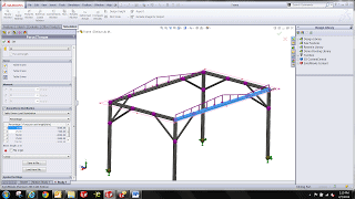
Total Load Distribution

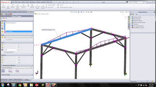
Table Driven Load Distribution
For more training and tutorials on the many 3D CAD Modeling solutions in the SolidWorks family of products and add-ons, register for an upcoming Event or look into our SOLIDWORKS training.

 Blog
Blog 


