Failure IS an option. Exploring Advanced Material Models on the 3DEXPERIENCE Platform
Finite Element Analysis (FEA) has been used for decades to help engineers understand how parts and the materials they are made from will behave in real life. In most cases, the analyst is looking for stresses that exceed yield or strain higher than the failure rating of the material. This is a tried-and-true method that is standard in the industry. What happens when it is necessary to understand not just where the part will fail, but HOW it will fail? Furthermore, how does that failure propagate through the part material? These are difficult questions that usually require heavy investment in software, testing, and expertise to answer. Using 3DEXPERIENCE Structural tools, solutions to these questions are now easier to answer and more accessible than ever! Let’s take a look.
Fracture and damage mechanics are nothing new to the experienced ABAQUS user but have been unattainable for CAD-embedded simulation tools like SOLIDWORKS Simulation. 3DEXPERIENCE Structural simulation does a wonderful job of bringing both worlds together. To demonstrate damage and fracture, we are going to use the classic example of a Charpy test. If you are unfamiliar with the Charpy test, watch this video.
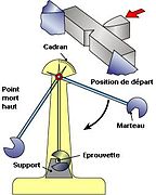
FIgure 1- Charpy Test
This Photo by Unknown Author is licensed under CC BY-SA
At a very basic level, the Charpy test is a way to determine the energy absorbed by a material during fracture. Simulating this process would be impossible with software that does not allow for fracture mechanics. So let’s take a look at the setup in 3DEXPERIENCE Structural simulation!
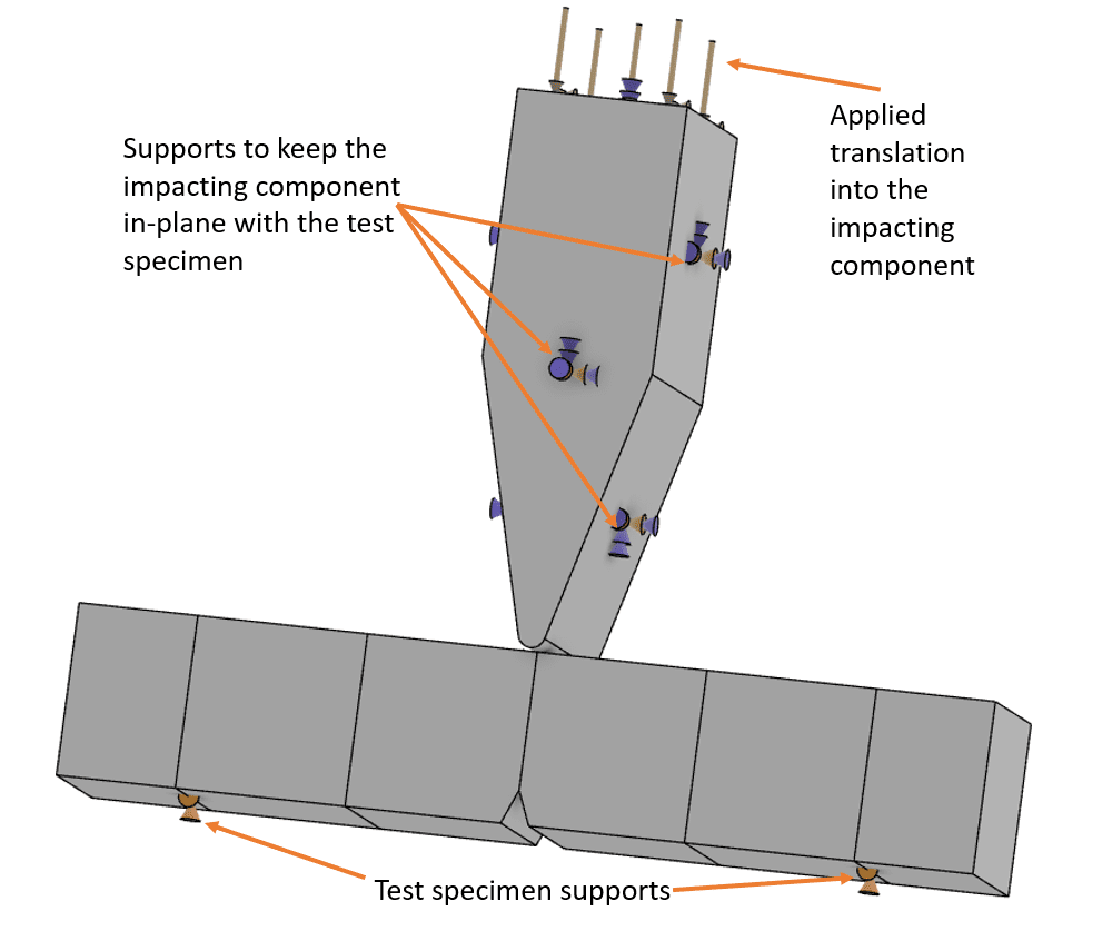
Figure 2
The setup is simple, hold the test specimen in place with simple supports, keep the impacting component in-plane with fixtures and apply the correct translation to it.
The impacting component will be treated as rigid, and the mesh must be sufficiently fine for the analysis to solve the fracture effectively. See the mesh plot below.
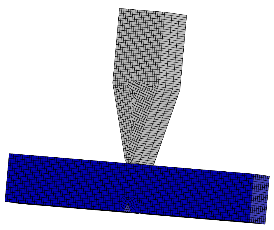
Figure 3
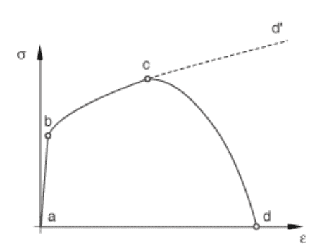
Figure 4
Finally, we can review the secret sauce. The ABAQUS backbone of 3DEXPERIENCE Structural simulation allows for the combination of multiple failure mechanisms to act simultaneously on the same material. According to the ABAQUS help documentation, the failure calculation mechanism can be broken into 4 parts:
- The material must have an effective description of the undamaged material response (a-b-c-d’ in figure 4)
- Must define a damage initiation criterion, i.e. how damage starts (c in figure 4)
- Must define how damage propagates once started (c-d in figure 4)
- Deletion of the element once the stiffness of the material is fully degraded. (d in figure 4)
Let’s go through those in order. In 3DEXPERIENCE Structural simulation, these four parameters are defined via the material’s data card. Because the material in question (aluminum) exhibits ductile behavior, we will use a ductile damage model for the failure analysis.
- Description of an effective undamaged material response. Our material has elastic and plastic material definitions assigned to the material’s behavior.
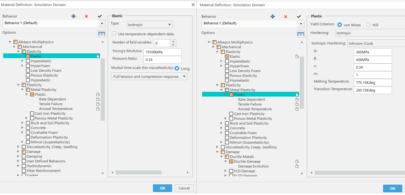
Figure 5
- The damage initiation criterion in this case is handled via a table that relates fracture strain, stress triaxiality, and strain rate. This is a complex subject beyond the scope of this blog, but you can see the data for our material below:
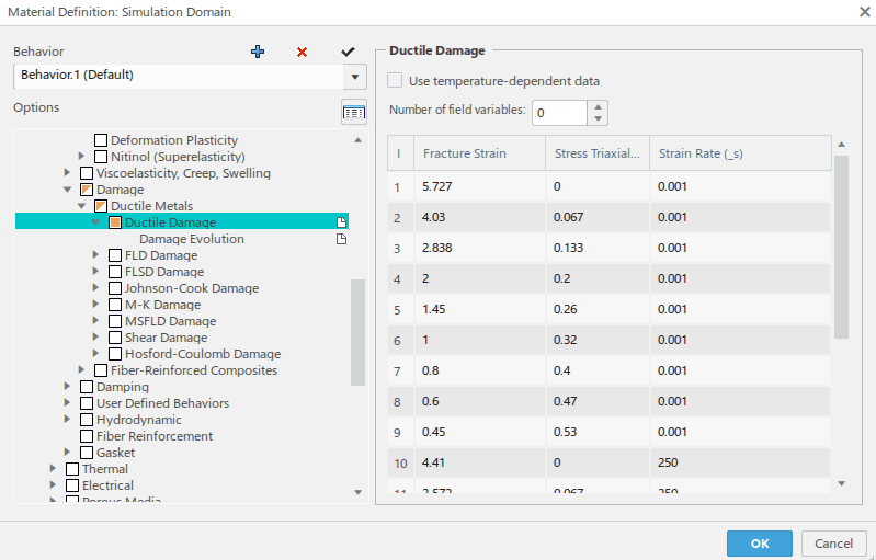
Figure 6
- Damage propagation is a numerical tool used by the ABAQUS solver to stabilize the fracturing elements so that the solution is more easily solvable. It can be defined as either a displacement or energy dependent parameter. For this model, we are using a 0.1 mm displacement at failure metric.
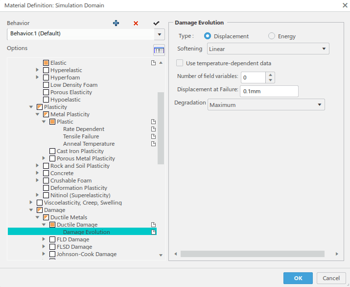
Figure 7
- The final piece of the puzzle is telling 3DEXPERIENCE Structural simulation what to do with the elements that meet the criteria above. In our case, I have turned on the “Remove Failed Elements” option so that the destroyed material is deleted from the FEA mesh.
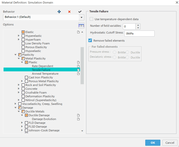
Figure 8
All that is left to do is run the study. Once it is finished, we can see our “Failure” in all its glory!
As you can see, this is an INCREDBILY slowed down animation. Notice that when elements reach a certain threshold, they are removed from the mesh allowing for the next layer of elements to be removed, and so on.
I hope this blog has helped to broaden your understanding of fracture mechanics using 3DEXPERIENCE Structural simulation. This technology truly is fascinating and making it more accessible to designers and analysts alike is a win-win. The next time your business needs to succeed by failing (materials), don’t hesitate to reach out to CATI!
Matt Sherak
Sr. Simulation Product Specialist Elite AE
Computer Aided Technology