How Do I Create a SOLIDWORKS Flow Simulation Project?
How do I create a Flow Simulation analysis project? SOLIDWORKS Flow Simulation is a computational fluid dynamics (CFD) analysis software. Flow Simulation provides an understanding of fluid motion around or through your design. Flow Simulation contains a conjugate heat transfer solver, parametric optimization, rotating regions with sliding mesh, free surface capabilities and many other options. In this article we are going to focus on getting started in Flow Simulation, and the steps to take to ensure a successful analysis.
First Step to a flow analysis is to turn on the Flow Simulation Add-In. This can be found next to the options at the top of the screen or at the Add-Ins command manager tab.
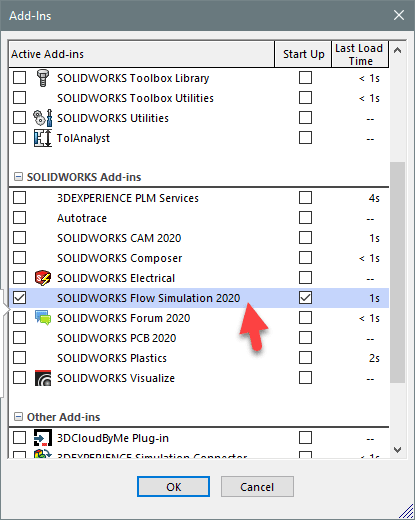
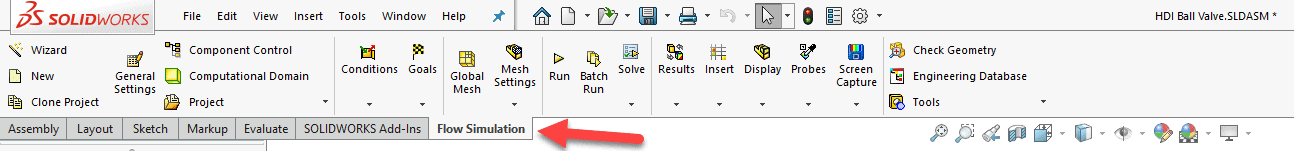
Adding in Flow Simulation opens a tab on the command manager dedicated to Flow.
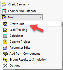
The next step to a SOLIDWORKS Flow Simulation analysis is to prepare the geometry. Let us assume that the analysis we want to complete is an internal analysis and that lids have been placed in the model using the Create Lids tool to enclose the internal volume.
![]()
SOLIDWORKS Flow Simulation provides a Setup Wizard to start your project. The Setup Wizard guides you through the settings you will need to complete a successful Flow study.
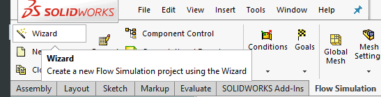
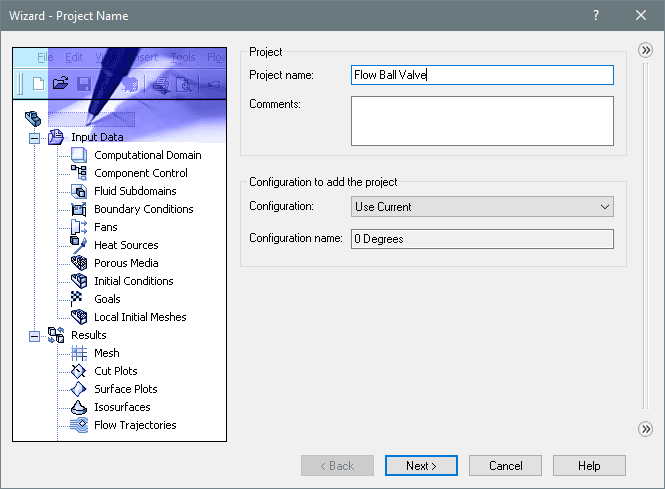
With the Wizard open, step through the setup choosing the options for the project as you go. Name your project and choose the configuration of the model you wish to analyze. Choose Next to move onto the next step.
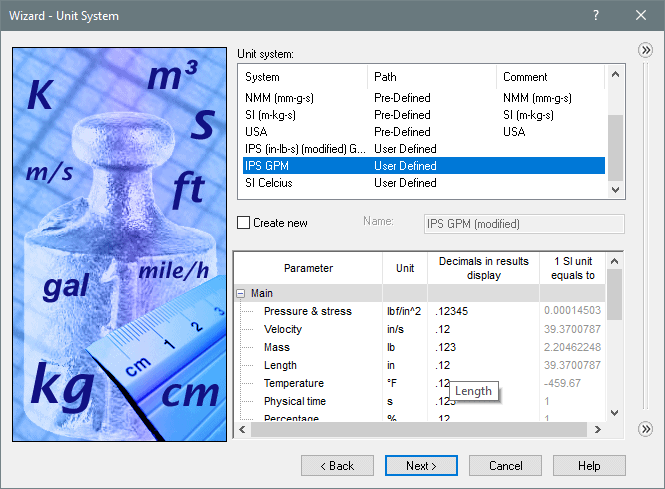
Pick the project’s Units. Note that you can mix and match units according to your needs.
Choose the analysis region. Internal analyzes the fluid inside the geometry, external analyzes the fluid outside, and inside the geometry.
Checking the boxes gives you more options for the analysis.
- Heat conduction in solids: turns on the thermal solver and allows for conduction and convection to be calculated.
- Radiation: enables the radiation characteristics of the geometry and accounts for the radiative thermal properties.
- Time dependent: switches from the default steady state to a transient analysis.
- Gravity: enable natural buoyancy effects.
- Rotation: activates the rotating regions capability including, global, local averaging, and sliding.
- Free surface: permits immiscible fluids.
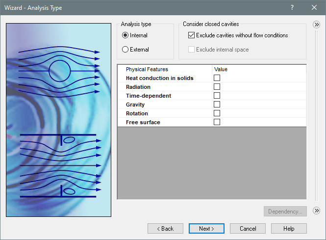
We will keep it simple for this analysis by keeping the project internal and steady state.
Next, choose the fluid or fluids you wish to use in the analysis. In this case water was added. 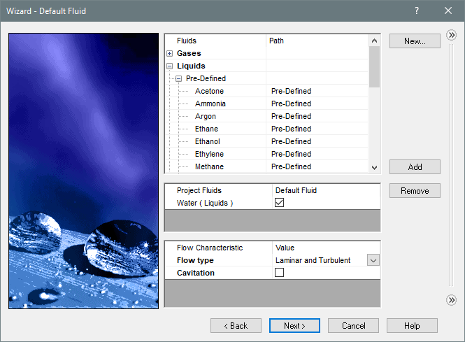
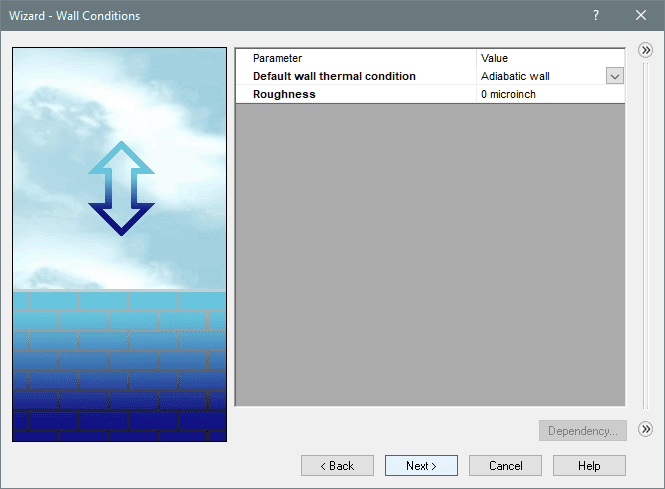
The default roughness and wall condition are accepted as they do not affect this analysis.
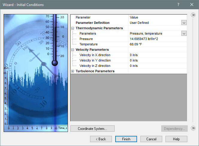
The default initial conditions are accepted as well, indicating atmospheric pressure to be at sea level, and room temperature.
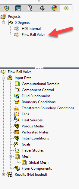
When the Wizard closes, a new project will start located in the Flow Simulation tab of the feature manager tree.
Add the boundary conditions that apply to your project’s problem statement. In this case a 20gpm flow rate of water enters the valve and exits through the opposite opening at environmental pressure.
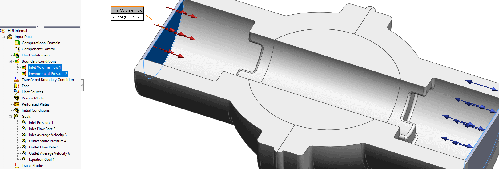
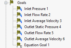
Assign goals to monitor important output values such as volume flow rate, velocity, and pressure.
Run the project and view the results. We will cover more on the setup and results options in additional blogs. 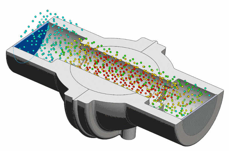
That is all. The setup is that easy. Let SOLIDWORKS Flow Simulation do the heavy lifting and provide valuable insight to your Fluid Flow Designs. It is important to know how your design performs and Flow Simulation provides information a flow benchmark, or wind tunnel just cannot provide.
This blog has an accompanying video under the same title. Check out the Computer Aided Technology video page for more information and subscribe.
Robert Warren
Simulation Specialist, Elite Application Engineer
Computer Aided Technology, Inc.