How Do I Post Process a SOLIDWORKS Plastics Shell Meshed Study
How do I post process a SOLIDWORKS Plastics shell mesh study? Utilizing the analysis capabilities of SOLIDWORKS Plastics early in the product development cycle enables users to optimize the plastic injection molding process, create high quality parts, and reduce manufacturing costs. Now that the study has been solved, what’s next? Clean up the SOLIDWORKS graphics window? Gather data for inlet pressure or clamp force? Create animations? There are many post processing options for a shell meshed, SOLIDWORKS Plastics study. Here are a few to consider.
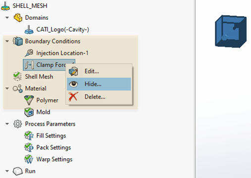
Hide/Show Icons
Some boundary condition icons may clutter the SOLIDWORKS graphics window or hide the upper end of the legend. To hide any boundary condition, right-click on the icon from the SOLIDWORKS Plastics feature tree.
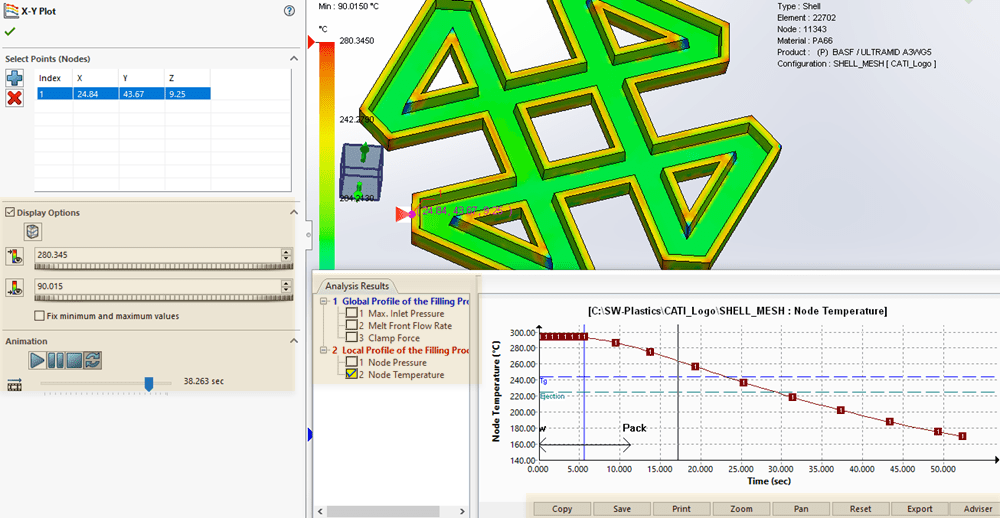
Read XY Plots
Accessing results outside of the saved data files can be accomplished using XY Plots. XY Plots allow users to review maximum inlet pressure, melt front flow rate, and clamp force data during the injection molding process. It is also possible to track the pressure and temperature of nodes. To manually zoom this plot data, use the middle mouse wheel. Panning the plot uses the right mouse button. Alternately, use any of the buttons along the bottom edge of the X-Y Plot window or to reset the plot back to the default size.
When reviewing nodal pressure or nodal temperature data, select nodes of the SOLIDWORKS Plastics mesh from the graphics window. It is possible to view animations of these results from the Display Options section of the property manager.
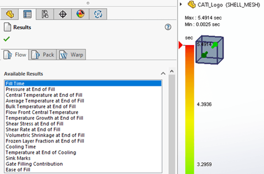
FLOW-PACK-WARP Results – Animation
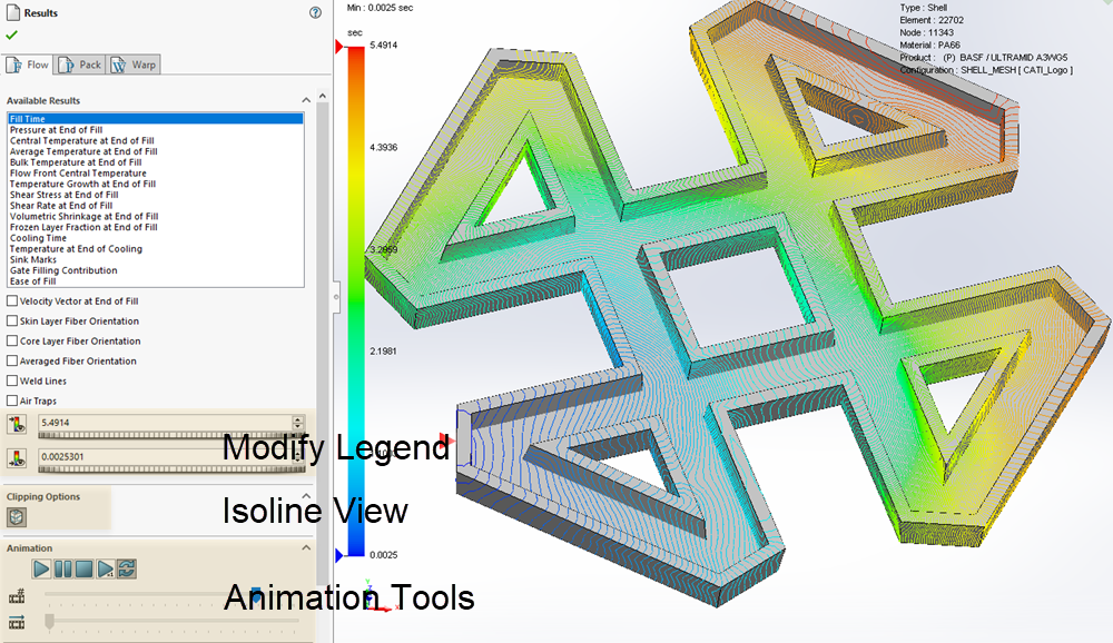
Some result quantities can be animated, like the Fill Time plot. I believe the animation tools are intuitive. My only complaint is that a 1 to 1 playback speed setting does not exist. The default view for results is a contour plot, however, with a shell meshed plastics study it is possible to show Isolines mapped onto the surface of the model.
Occasionally, it is necessary to modify the extents of the plot legend to better understand and visualize a result. This is easily accomplished by changing the numbers in the property manager for the result plot. Either drag the change bars beneath each number or manually type in a value. To reset the values to the extents, click the small icon to the left of the maximum and minimum values.
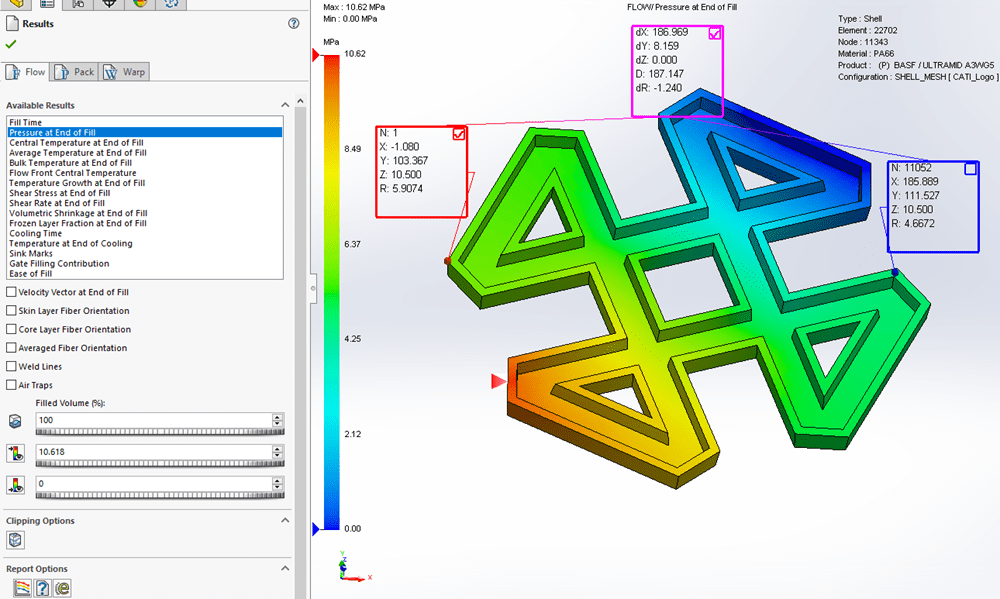
FLOW-PACK-WARP Results – Measure Tool
Utilizing the Measure tool in SOLIDWORKS Plastics, found on the SOLIDWORKS Plastics command manager tab, allows users to gather data at specific locations. Make either the red or blue box active by clicking on the check box in the upper, right corner of either box. The data in these two boxes are the node number, the X, Y, and Z Cartesian locations of the node measured from the part origin, and the data quantity for the selected node. The magenta dialog box represents the Cartesian space distance in X, Y, and Z, the straight-line distance, and the difference in values between the selected nodes.
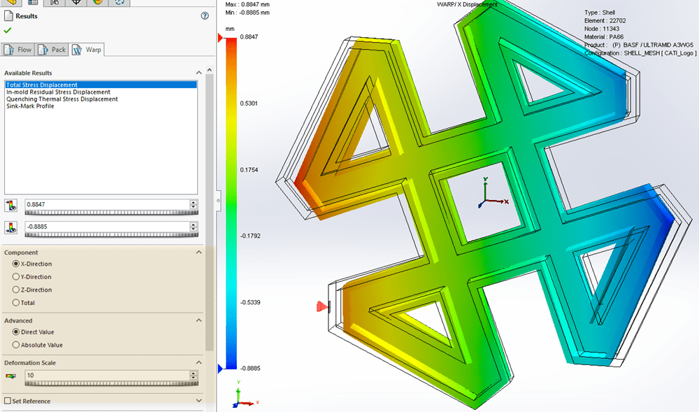
FLOW-PACK-WARP Results – Warp
Reviewing Warp analysis results may be difficult at the default scale. To adjust this, expand the Deformation Scale section and increase the default value. The Component section of the Property Manager changes resultant warp values to data specific to the X, Y, or Z axis directions to aid in visualizing the results.
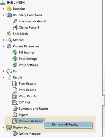
Remove All Results
What if a mistake is found in the setup of the SOLIDWORKS Plastics project or additional boundary conditions need to be included for a more accurate analysis? When many setup changes are required, the changes can be made a lot faster by deleting the existing result files. Right click on the icon and confirm the selection in the pop-up window.
To learn more about SOLIDWORKS Plastics post processing, we invite you to attend a CATI training course. The above post-processing tools, as well as a few others, are shown in the accompanying video under the same title. Check out the Computer Aided Technology video page for more information and subscribe! Now go make your products better with SOLIDWORKS Simulation!
Bill Reuss
Product Specialist, Simulation
Father, Golf Junkie, Coffee Connoisseur, Computer Nerd
Computer Aided Technology, Inc.