How Would You Like a Bolt Sandwich from SOLIDWORKS?
Bolted connections are used in many industries for a wide variety of applications. Look around and you will see fasteners used in automobiles, furniture, appliances, electronics, medical devices, construction, and many other design applications. If you have worked in Engineering and design long enough, chances are you have designed a non-permanent joint using fasteners. Like me, you may have needed to solve a finite element model that included fasteners and get accurate results for design verification and validation activities. I’m going to explain how to correct a common mistake in setting up a bolted joint with more than two components, a bolt sandwich!
My simple SOLIDWORKS CAD assembly has three plates. The top plate has two M5 counterbore holes while the middle and bottom plate have two M5 clearance holes. The mate scheme aligns the series of holes to be concentric and the opposing faces coincide with one another. I used SOLIDWORKS Toolbox and Smart Fasteners to add the appropriate bolts with the top and bottom stack components. My next step is to set up a Linear Static analysis using SOLIDWORKS Simulation to analyze the bolted connection of this simple assembly. The setup of the bolt connectors was done automatically by using the ‘Convert Toolbox fasteners to bolt connectors’ option (Figure 1).
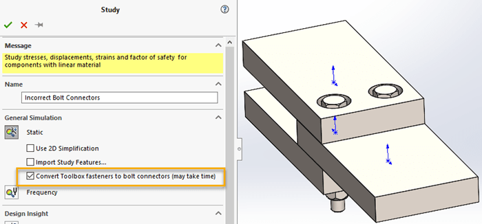
Figure 1
The toolbox fastener conversion takes a few seconds, but it sure beats manually adding multiple virtual connectors to a finite element study! Figure 2 shows the correct selection of edges for the counterbore bolt and nut fastener stack used for the virtual bolt connector. The head diameter, nut diameter, and nominal shank diameter are set based upon the Smart Fasteners used in the assembly. Notice the bottom section of the Property Manager for Advanced Options is empty.
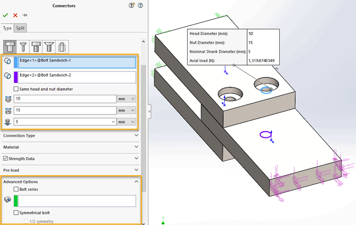
Figure 2
Other details for the finite element model include two fixed restraints on the top and bottom plates, a force on the end of the middle plate, and appropriate no penetration contact conditions applied between the coincident faces. Most users would be comfortable with the setup I have described and would proceed to mesh and solve this finite element model. There are two likely outcomes when the finite element model, as described, is solved. One possibility is an error message that the model is unstable, unable to be solved (Figure 3).
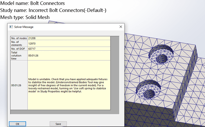
Figure 3
Alternately, you may receive the “large displacement warning” message. If this occurs and you clicked ‘no’ to the warning, a result will be generated. When you review the displacement results, it is apparent that the solution is incorrect (Figure 4). I think we can all agree that 172 trillion millimeters is an incorrect displacement result! Well, incorrect unless you were expecting one component to fly nearly half the distance to the moon!
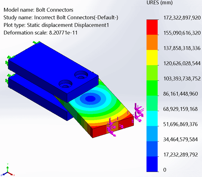
Figure 4
As a small aside, if the no penetration contacts included friction the study may solve to completion and appear correct. You would need to thoroughly investigate the displacement results to identify the issue with the finite element model setup. More specifically, you would need to look at directional displacement plots and verify that the bolt holes became misaligned.
The problem in the bolt connector setup is the sandwich of components. Using the option for automatic toolbox fasteners gets most of the setup correct, but the middle component is not automatically recognized in SOLIDWORKS Simulation. To correct the automatic setup of the bolt connector, or even a manual setup, you need to define the sandwich component(s) for SOLIDWORKS Simulation to accurately analyze the fastener joint. This is accomplished when editing the bolt connector by expanding the Advanced Options section of the Property Manager, checking the ‘Bolt Series’ box, and selecting the cylindrical face of the hole for the sandwich component(s) (Figure 5). This needs to be done to all connections with three or more components fastened together with virtual bolts.
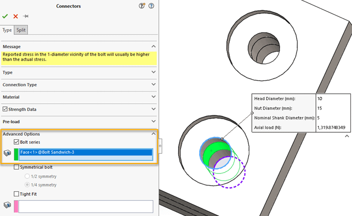
Figure 5
After making the appropriate changes, then re-meshing and solving the finite element model, the results are now correct. The additional face selection for the bolted connection keeps the cylindrical faces nearly aligned concentrically. Reviewing a resultant displacement plot shows that the middle sandwich component was held in place by the bolt connectors (Figure 6).
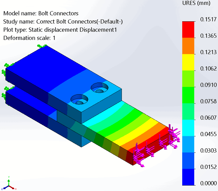
Figure 6
A better view of the correct bolt connector results can be seen by using the Advanced Options section of the displacement plot property manager “Show plot only on selected entities” and choosing the bolt hole faces. In Figure 7, I have created an x-direction displacement plot for these faces that indicates some sliding of the sandwiched component, leading to a minor misalignment of the bolt holes.
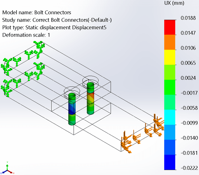
Figure 7
The next time you need to solve a bolted connection, I hope you spend some extra time in the virtual fastener setup to make certain it will solve correctly. When you do that, the bolt sandwich won’t smack you in the face with analysis errors. Now go make your products better with SOLIDWORKS Simulation!
Bill Reuss
Product Specialist, Simulation
Father, Golf Junkie, Coffee Connoisseur, Computer Nerd
Computer Aided Technology, Inc.