Modeling fans in SOLIDWORKS Flow Simulation
There are a few ways to model fans or impellers in SOLIDWORKS Flow Simulation. The most accurate method involves modeling the actual fan/impeller blades and solving the study as a sliding mesh (rotating reference frame) problem. In this type of analysis, the mesh moves from one time-step to the next. This is a transient analysis and consumes a considerable amount of computational resource, typically resulting in exceedingly long solution times. This type of analysis is recommended for fan manufacturers who are trying to simulate the effect of changes to the fan geometry on the performance of the fan or pump manufacturers aiming to accurately calculate hydraulic head. It is not recommended for the novice user or someone who is simply trying to simulate the effect of a supplied fan component that moves air (typically for cooling or ventilation purposes) in a flow application.
This blog will focus on the simpler and easier way to model the effect of a fan on fluid flow, using a “Fan” component in the flow simulation project tree. Fan components do not attempt to physically model spinning fan blades. Rather, they use fan curve data provided by the manufacturer to create an output volume or mass flow rate based on the pressure difference between the inlet and outlet faces of the fan.
To add a fan component to your SOLIDWORKS Flow Simulation project, first make sure the “Fans” folder shows up in your project tree. If you do not see a “Fans” folder, then right mouse click on your project name at the top of the project tree, and then click “Customize Tree.”

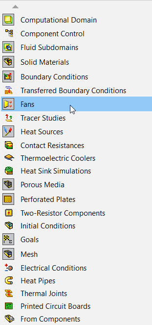
Then select “Fans” from the list of available options, which will add the “Fans” folder to the project tree.
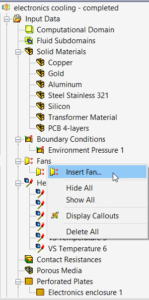
To insert a new fan, right click on the “Fans” folder and then select “Insert Fan.”
Once inside the Fan property manager, note that there are three options for Fan type, namely External Inlet Fan, External Outlet Fan, and Internal Fan. For the External Inlet Fan, you only need to select the faces where fluid exits the fan and enters the domain. In this case one would typically use the face of a lid at the inlet opening. Similarly, for an External Outlet Fan you will need to select faces where fluid enters the fan and exits the domain. Again, one would typically use the face of a lid at the outlet opening. For an Internal Fan, you will need to select the faces where fluid both enters and exits the fan and prepare the CAD geometry accordingly. This is the more interesting case that I will explore further in this blog. Some of the options available in the fan property manager are shown below.
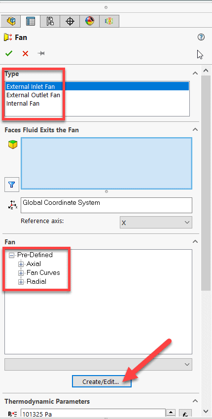
SOLIDWORKS Flow Simulation includes a large database of standard fans from a variety of manufacturers. Search for your fan make and model in the included database from the list of “Pre-Defined” fans. If your particular fan is not included in the database, then you will need to enter the fan curve data yourself by clicking on the “Create/Edit…” button in the property manager. This will open the Engineering Database.
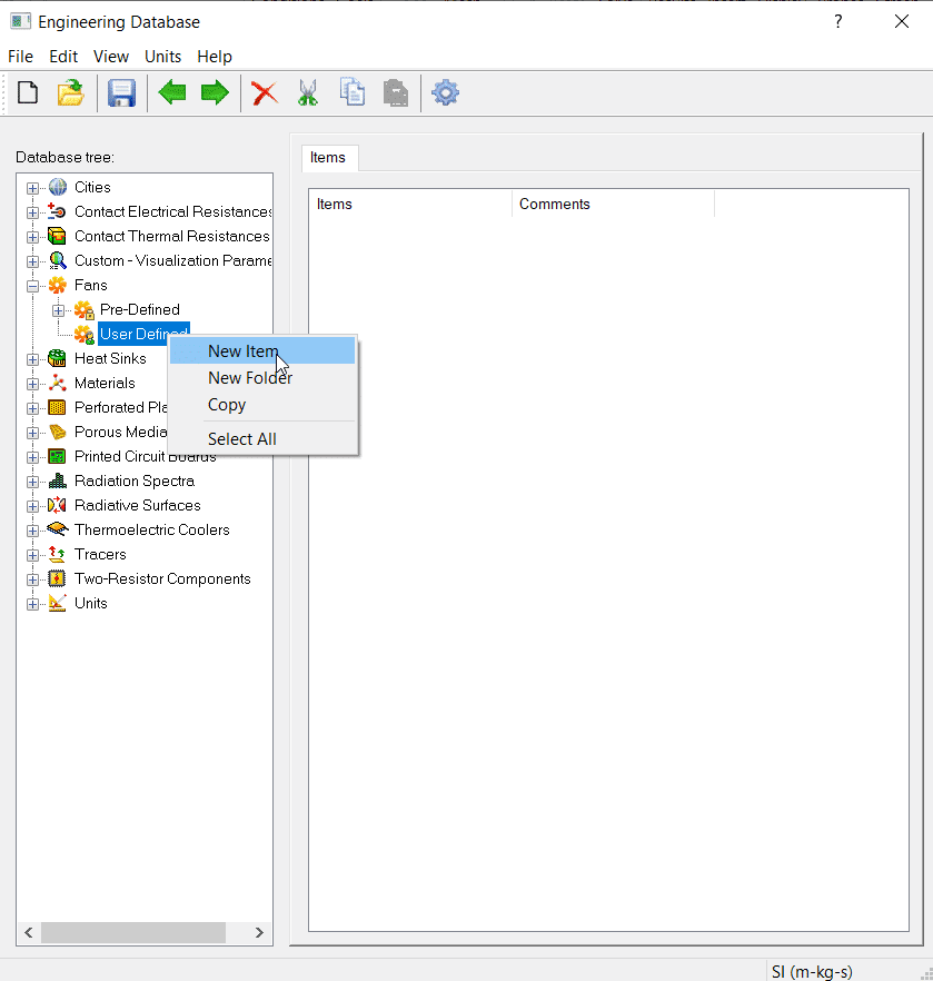
Create a custom fan by expanding the “Fans” folder, right clicking on “User-Defined” and then selecting “New Item.”
Before adding an internal fan to your project (regardless of whether it is one of the pre-defined fans already included in the engineering database or one you will manually create by entering the fan curve data yourself), it is critical to first prepare your fan geometry appropriately. The inside of the fan can be thought of as a “black box;” the geometrical details inside the fan housing are not needed since the performance of the fan is entirely governed by the fan curve data.
If your SOLIDWORKS 3D CAD model or assembly contains the actual fan blades, you must create a simplified version of the geometry that only models the housing, and the inlet and outlet faces. Creating a “CFD” configuration of the fan in CAD that eliminates the actual blades is the recommended workflow.
There are 3 fan variations available, namely Axial, Fan Curve and Radial.
Axial fan definition
Axial fans push out air parallel to the rotation axis of the blade. The image below shows a typical axial fan, including the housing and the blades.
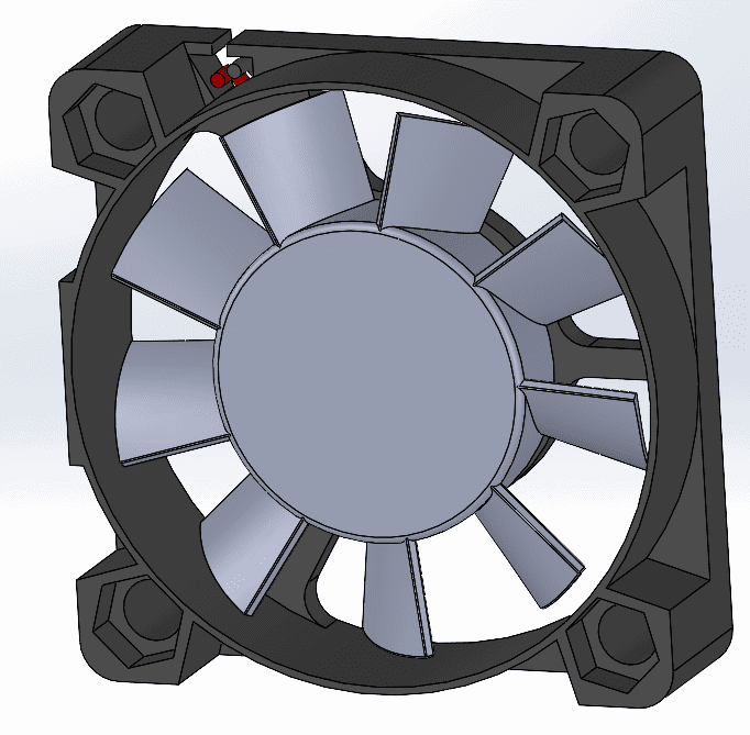
Detailed axial fan geometry
To include an internal axial fan like this in your flow simulation project, create a very simple configuration that eliminates the fan blades and the small geometrical details of the housing that have negligible impact on the actual flow. Create split faces on the front and back faces of the housing (highlighted in blue) to represent the inlet and outlet. In this case, since the hub is large, our outlet face is donut shaped.
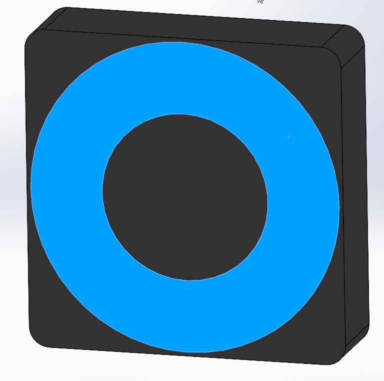
Outlet face

Inlet faces
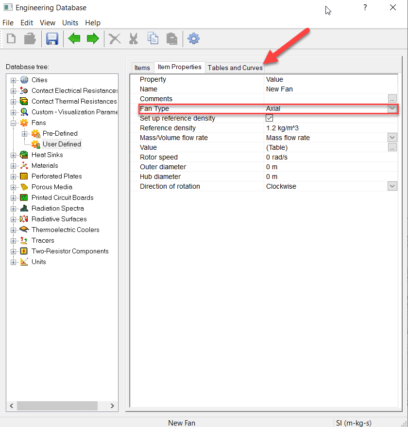
Choose the “Axial” option from the drop-down list of options under “Fan Type.” Key in appropriate values for the Outer diameter, Hub diameter and Direction of Rotation. These additional parameters are used to calculate flow swirling if the user chooses to include swirling effects in the calculation. Click on the “Tables and Curves” tab to enter the fan curve data from the manufacturer.
Radial fan
Radial fans (often called centrifugal fans) move air from the center radially. They are typically housed inside of a volute. However, the radial fan option in SOLIDWORKS Flow Simulation should only be used for radial fans that are not enclosed inside a volute. If your radial fan is enclosed inside a volute, then use the Fan Curve option instead. See solution ID S-049263 in the SOLIDWORKS Knowledge Base for more information.
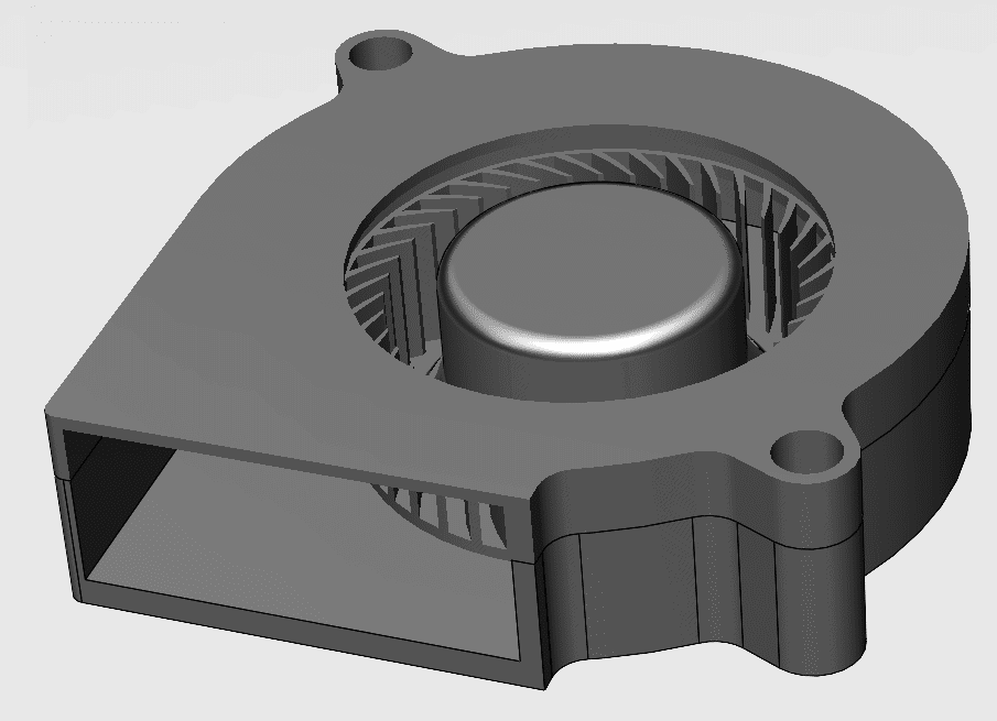
The image below shows a typical radial fan, including the housing and the blades.
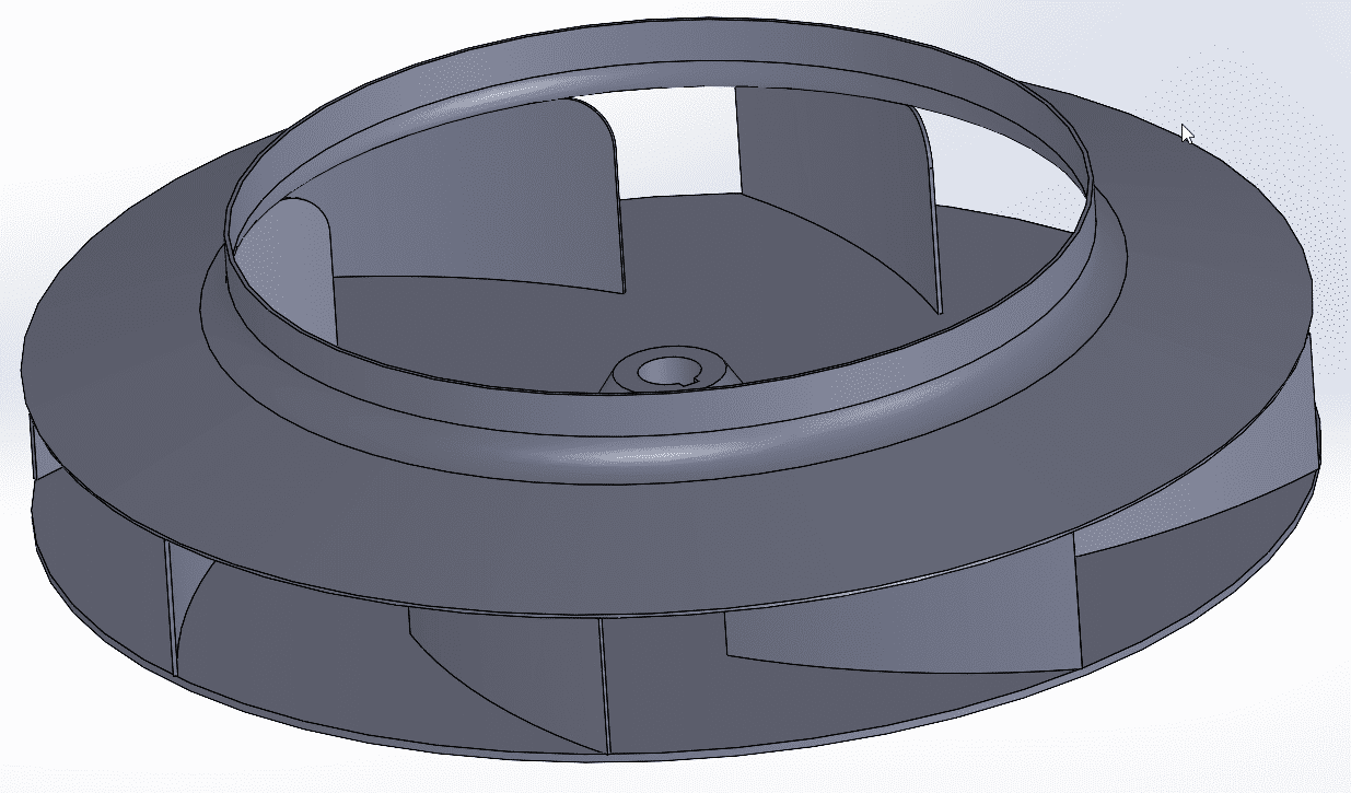
Detailed radial fan geometry
To model this in Flow Simulation, create a revolved solid body with the same O.D. as the blade tips, as shown below. Select the top circular face for the inlet and the cylindrical outside face as the outlet.
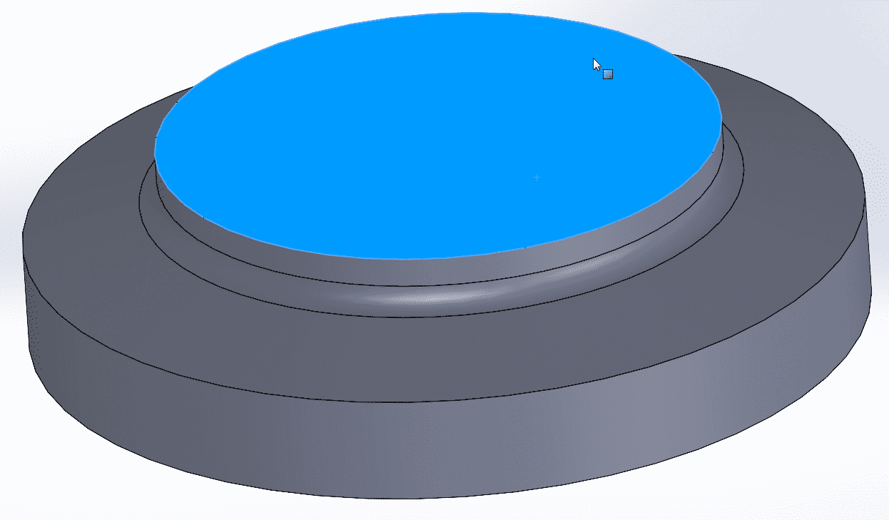
Inlet face
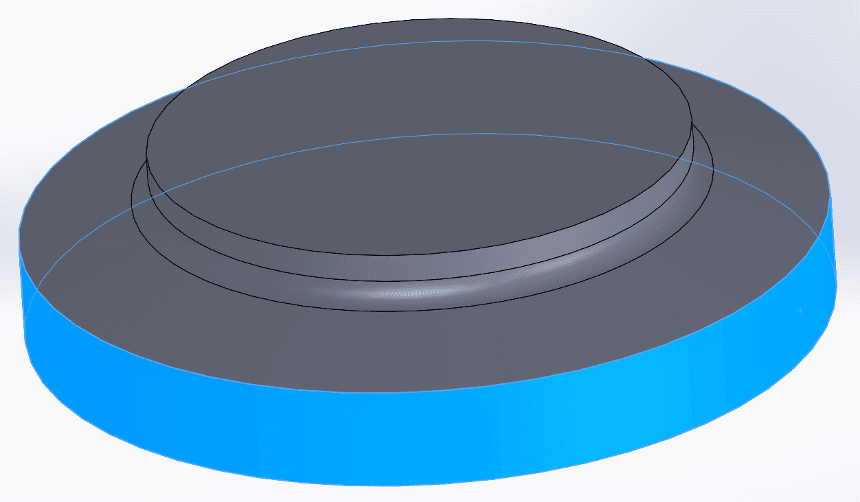
Outlet face
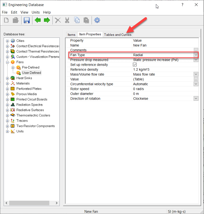
Choose the “Radial” option from the drop-down list of options under “Fan Type.” Key in appropriate values for the Outer diameter, Rotor Speed and Direction of Rotation. These additional parameters are used to calculate flow swirling if the user chooses to include swirling effects in the calculation. Click on the “Tables and Curves” tab to enter the fan curve data from the manufacturer.
Fan curve option
The generic fan curve option should be used for radial fans housed inside a volute or other fan types that do not fall specifically into the radial or axial category. The image below shows a typical blower fan, including the housing, volute, and the blades.
Detailed blower fan geometry including volute
To model this as an internal fan in SOLIDWORKS Flow Simulation, create a solid body with the same shape as the volute and split faces to represent the inlet and outlet surfaces. Select the top donut shaped face for the inlet and the rectangular downstream face as the outlet.
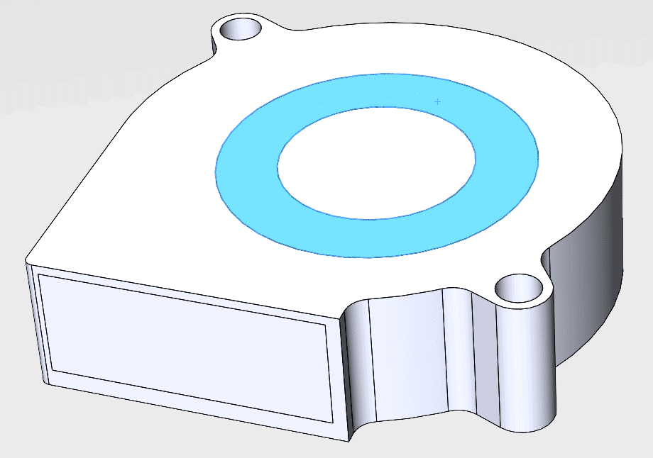
Inlet face
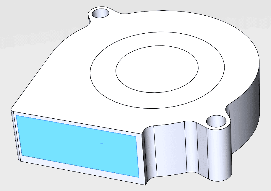
Outlet face
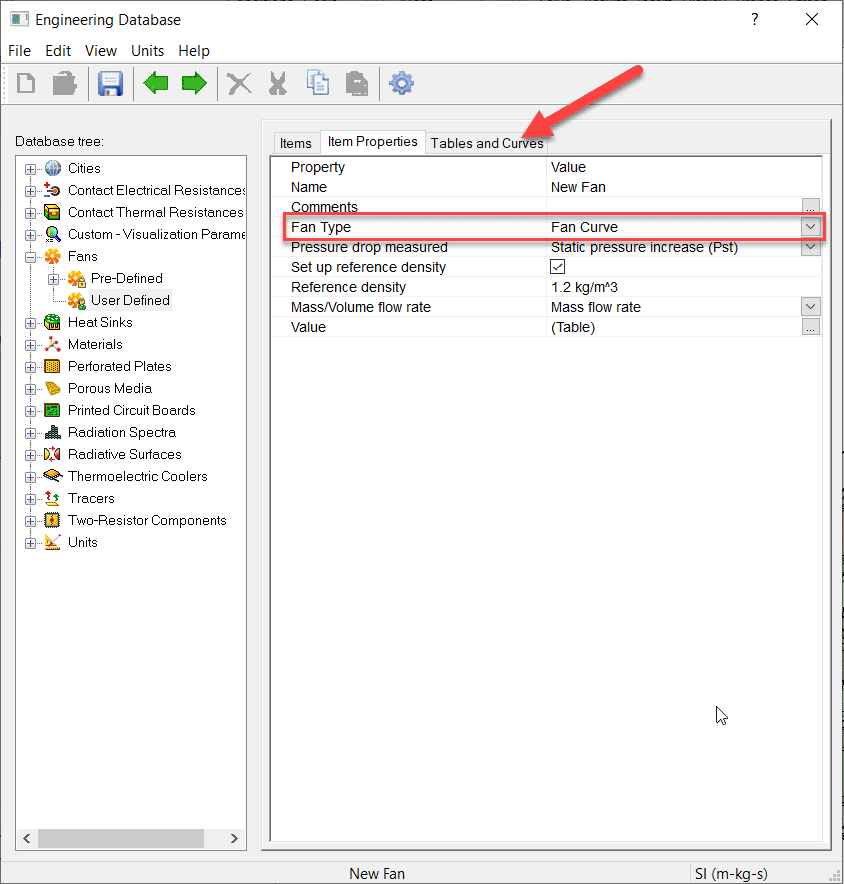
Choose the generic “Fan Curve” option from the drop-down list of options under “Fan Type.” Click on the “Tables and Curves” tab to enter the fan curve data from the manufacturer.
When using Fan components in a SOLIDWORKS Flow Simulation study it is important to prepare your CAD geometry correctly and choose the right fan type that matches your geometry definition. I hope this blog will shed some light on the right way to perform these steps.
Alon Finkelstein
Simulation Product Specialist
Computer Aided Technology, Inc.