Napkin Sketches, Hand Calculations and… SOLIDWORKS Simulation?
Why do we Designers and Engineers resort to napkin sketches and hand calculations? Some people would say it is because we are gluttons for punishment! Other people might recognize that a napkin sketch is a great way to convey a new idea quickly. Still others might voice an opinion that hand calculations provide quick insight into performance. Whatever your reason for resorting to a napkin sketch or hand calculation is, I say keep doing it! What do either of these have to do with analysis? Let me explain.
You probably know how to create weldment designs using SOLIDWORKS CAD. If you analyze a weldment using SOLIDWORKS Simulation, structural members are automatically meshed with beam elements. A beam element is a one-dimensional simplification of the CAD geometry, utilizing the section properties of the structural member in the calculations. This simplification allows us to create what amounts to a hand calculation in SOLIDWORKS Simulation.
Take, for instance, the table shown in Figure 1. The table might have a single structural member profile used for the legs and braces, such as square tubing. Let’s say the table design details are nearly complete, with multiple trims and extends to generate the cut list. These steps are necessary to fully detail the design, possibly create drawings, or even generate product renderings.
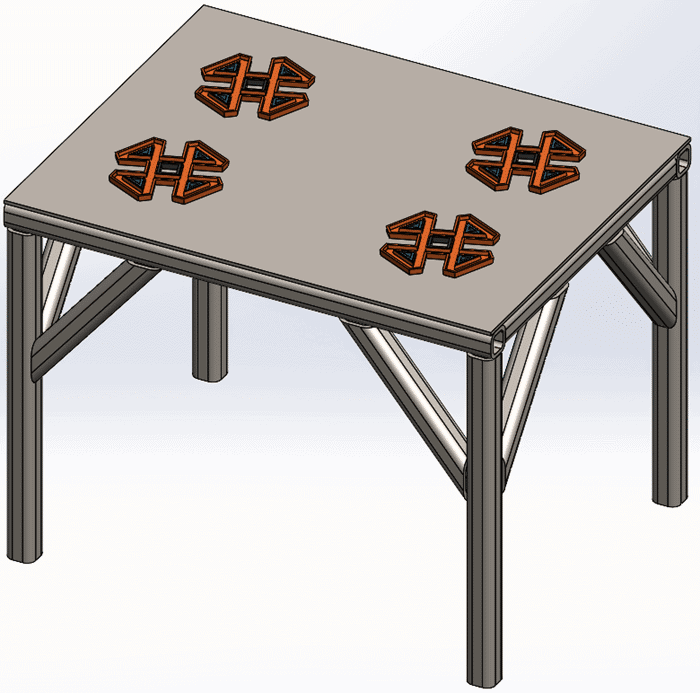
Figure 1.
There are likely a few additional items I need to finalize the project, such as end caps and mounting pads for the table legs. There is, of course, one thing I cannot leave out prior to finalizing any design – the analysis! I have also analyzed the table design in SOLIDWORKS Simulation and verified all performance criteria has been met (Figure 2).
Figure 2.
At this point in the design process, I would be feeling pretty good knowing that the end of the project is in sight! Feeling good right up until that time a wrench gets thrown into the process. That wrench is in the form of a napkin sketch where the square tubing has been replaced with, for instance, an I-beam. Now we, the Designers and Engineers, need to react. Quickly! Since I am using SOLIDWORKS, updating the structural member for the weldment is easy and fast. It’s the downstream features that might cause issues (Figure 3). In this instance, the errors occurred because the trim/extend features utilized faces of the square tubing to modify the design.
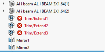
Figure 3.
While I highly recommend working on SOLIDWORKS Simulation studies using SOLIDWORKS CAD models without rebuild errors, this time there is a shortcut. I can solve the analysis without updating the geometry! Remember the section properties previously mentioned? If I right click on any structural member within the SOLIDWORKS Simulation Feature Tree, I can see what SOLIDWORKS Simulation is using for the square tubing section properties (Figure 4).
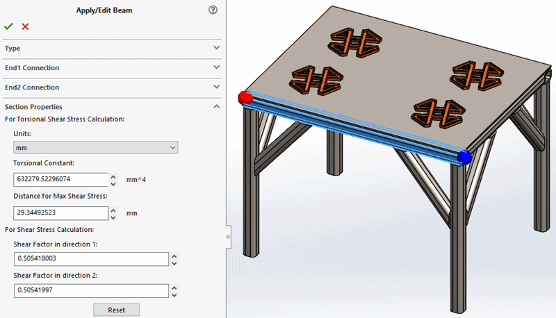
Figure 4.
This is where my virtual hand calculation begins. I need to know the section properties for the proposed design change to an I-beam. I utilized the Copy Study option in SOLIDWORKS Simulation, and then expanded the newly created SOLIDWORKS Simulation feature tree. After selecting any (or all) structural member(s), I then right-click and choose Edit Definition to access the Apply/Edit Beam property manager. Expanding the Section Properties portion of the property manager, I have access to the beam element properties. I typed in the updated values to reflect the design has “changed” to an I-beam (Figure 5). Notice that SOLIDWORKS Simulation indicates that I have manually defined the section properties for the analysis.
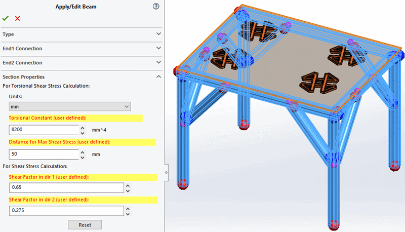
Figure 5.
My next steps are to re-mesh and re-solve the FEA study. Since I copied the original SOLIDWORKS Simulation study, all the post-processing content I had already created is available for comparing these new results to the original design (Figure 6).
Figure 6.
My next steps are to review the analysis output and verify the proposed design change will pass all design requirements. If the design passes, I can re-visit and update the SOLIDWORKS CAD model accordingly. If the design does not pass, I have saved time by not modifying and correcting the geometry and associated errors.
So do not shy away from napkin sketches and hand calculations when the opportunity presents itself! You might find a neat scenario where these activities can help you understand whether investing a lot of time in CAD geometry changes is warranted. If you are interested in learning more about beam elements in SOLIDWORKS Simulation, I recommend starting with Neutral Axis, Shear Center, and Beam Meshing in SOLIDWORKS Simulation written by my colleague, Kurt Kurtin. There are several other Computer Aided Technology blogs discussing beam elements, such as Beam Diagrams, Understanding Beam Diagrams, and Thermal Loads for Beam Elements. Now go make your products better with SOLIDWORKS Simulation!
Bill Reuss
Product Specialist, Simulation
Father, Golf Junkie, Coffee Connoisseur, Computer Nerd
Computer Aided Technology