Patterns: Changing Instance size with the Vary Sketch Option in SOLIDWORKS
SOLIDWORKS has always had many ways to create dynamic, powerful pattern features. Buried in the options since almost the beginning of time, and sometimes forgotten, has been a “Vary Sketch” option. Let’s explore this option a bit to show you some interesting ways to use it.
For a little bit of background, for the Vary Sketch to work it does require that the Pattern feature use a dimension from the seed feature sketch as a direction reference. That dimension is the key as what SOLIDWORKS is really going to do is change that dimension and rebuild the sketch for every instance of the pattern
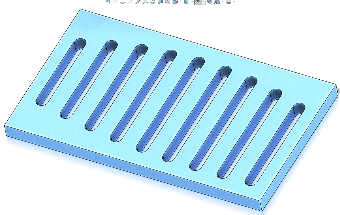
Here is a screenshot of the first example we’ll discuss today. As you can see the slot length varies for every instance. Let’s see how that is done.

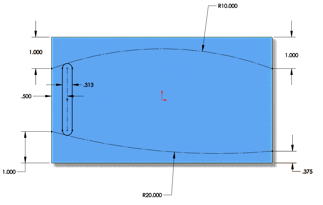
This starts with the sketch for the very first slot. If you notice in the sketch below the length of the slot is not defined. It is controlled by the position of the two Arcs. Those arcs act as layout sketches. That is the key to getting this pattern to work

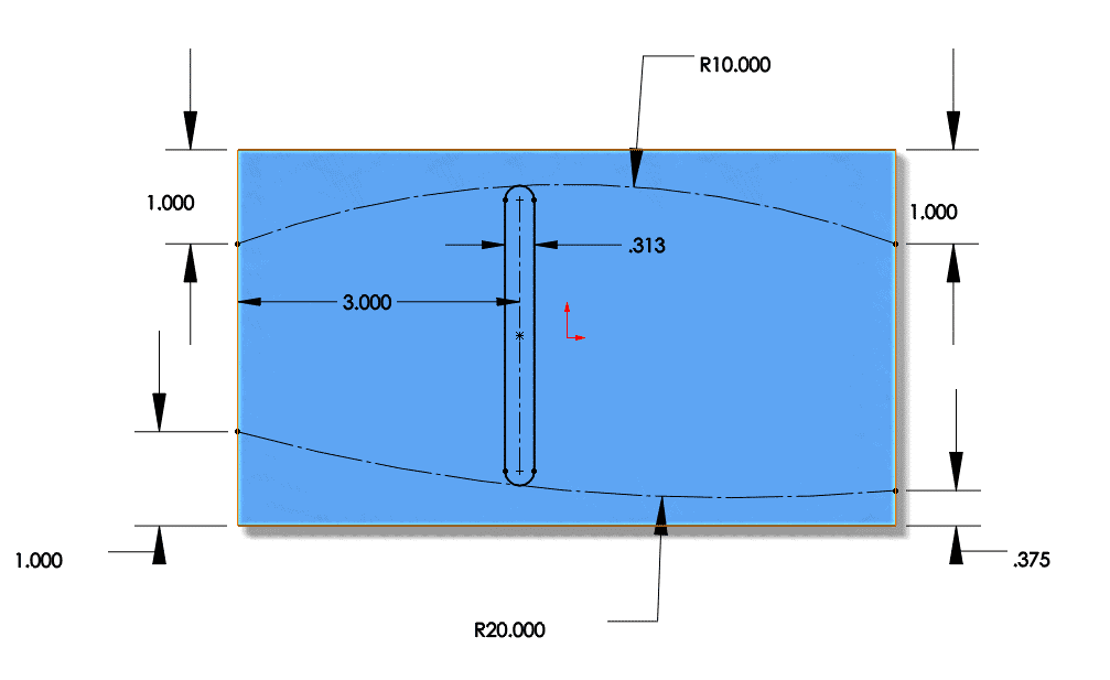
If we were to manually modify the 0.500 dimension on the left this is what would happen when SolidWorks recalculates the tangent relations on the slot

The pattern feature starts out life like any other feature. The important thing to remember is that direction one has to be the 0.500 dimension reference. Without that the Vary Sketch Option will be greyed out. Here is what the property manager will look like

There are two things to note. The first is that we are using Vary Sketch and not Instance to Vary. The second is that the preview is not automatically calculated. There is an option for Full Preview but as it may take some time to calculate you have to ask SOLIDWORKS to display it. With those options set, we will get the picture we see in the first screen shot
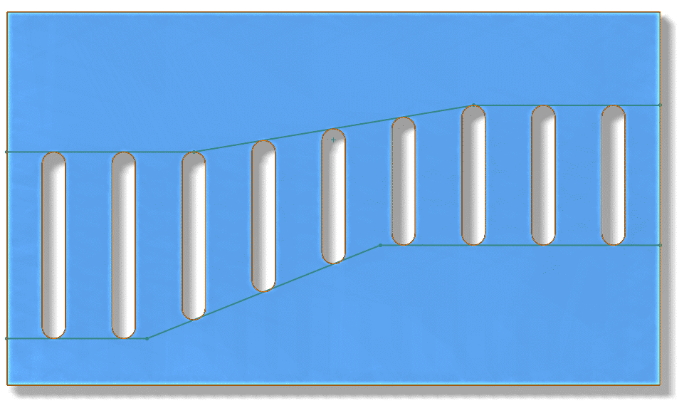
With a little creativity in the sketch this method can extrapolate out well. Here is another example

This particular example requires a little sketch tool called Fit Spline to work properly. That is a commonly used tool for people in Consumer Products who routinely use Surfacing Tools, but machine design users may not be as familiar with it. In the sketch you can see that the upper and lower curves seem to be made up of 3 linear segments each. That is true, and I made sure they were nicely defined. But I needed to make the slot Tangent to all 3 line segments at the same time – which is obviously impossible. The Fit Spline Tool will “trace” over any set of contiguous sketch entities with a single spline. It actually converts the original 3 lines to construction geometry but leaves them as defining entities so if you need to change the shape/size later you can. All you have to do is select your sketch entities and click Tools–> Spline Tools –> Fit Spline.
As you can see all the “magic” here stems from intelligent sketch work. The pattern feature itself is actually the simple part.
Hopefully you’ll be able to use this feature option in your design soon. I envision nicely styled cooling vents for your sheet metal enclosures in the near future.
Jay Pinheiro
Application Engineer Manager
Computer Aided Technology, Inc.

 Blog
Blog