Precise Placement of Forces and Fixtures
When working with SOLIDWORKS Simulation, exact positioning of fixtures and external loads is very important. Occasionally they are placed on entire faces such as pictured below.
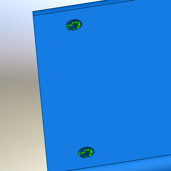
This however, is seldom the case. It is much more likely that the fixtures or external loads be placed on only a small portion of the face. This can be accomplished by using split lines. Split lines divide a face into multiple faces. This can be done as a part level feature or within the fixture or external load commands. The feature command can be found on the feature tab.

This will prompt the user to select a face to sketch on. Once the sketch is completed, the face/faces that are needed to be divided are selected and the new faces are created.
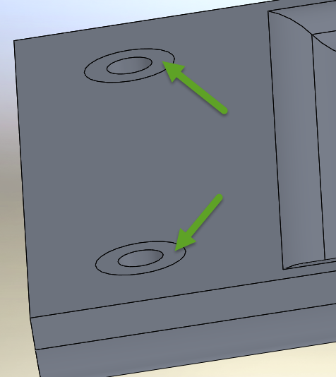
To create a split line within the fixture or external loads, the Split tab on the PropertyManager must be selected.
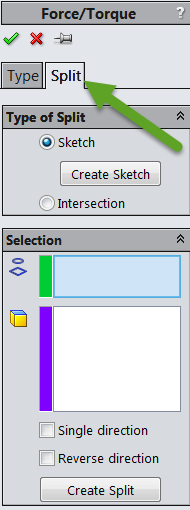
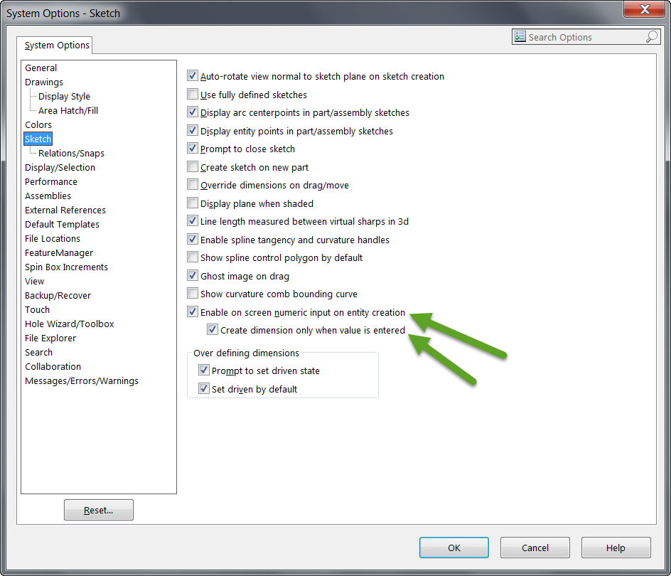
The sketch can then be created and the face to be divided chosen. One difference in using this method is that the dimension tools cannot be used. A workaround to this is making sure the on screen numeric input is turned on in options and using construction lines for positioning.
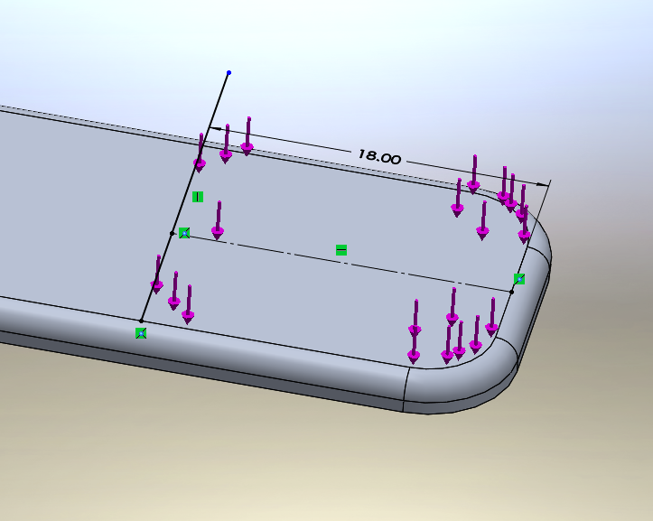
Using these methods, simulations can be much more exact and will provide the most accurate solutions.
Chad Whitbeck, CSWP
Applications Engineer, CATI

 Blog
Blog