Radiation in SOLIDWORKS Flow Simulation
I have been asked a lot recently about the radiation capabilities in Flow Simulation. No this isn’t the type of radiation depicted in the recent smash hit Chernobyl on HBO. In our case, we are concerned about electromagnetic (EM) radiation. In particular, the capability of EM radiation to transmit heat energy. Of the 3 modes of heat transfer (conduction, convection, and radiation), radiative transfer is perhaps the most overlooked in simulation. I decided to go into a bit more detail in this blog about the basics of radiative heat transfer in SOLIDWORKS Flow Simulation.
For starters, SOLIDWORKS Flow Simulation has two separate Radiation models that it uses. Discrete Transfer and Discrete Ordinates. There is a useful chart that compares the two methods on page 24 of the 2019 Flow Simulation Technical Reference document. See below:
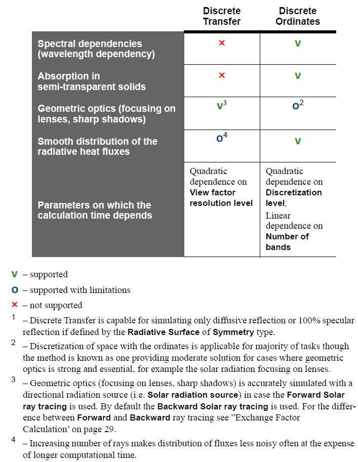
The Discrete Ordinates method is only included with the HVAC Module of SOLIDWORKS Flow Simulation, and as such will be covered in a later blog. For now, we are going to focus on the Discrete Transfer Method included with every level of SOLIDWORKS Flow Simulation. This first blog will cover a lot of theory but don’t despair, there is no test at the end!
Radiation is calculated based on the Stephan-Boltzmann Law of blackbody radiation. As a refresher, it states that the radiative heat power is proportional to the object’s surface temperature to the fourth power. See below

This is true where Q is radiative heat loss, ε is the emissivity (scale of 0 to 1, 1 being a perfect blackbody emitter), σ is the Stephan-Boltzmann constant (5.6703e-8 W/m^2K), T is the object’s surface temperature, and A is the surface area.
All bodies transmit radiation at all temperatures. Capturing the emission and absorption of radiation is crucial to thermal analysis.
As proof of what was stated above, I made a simple model to correlate SOLIDWORKS Flow Simulation to hand calculations.
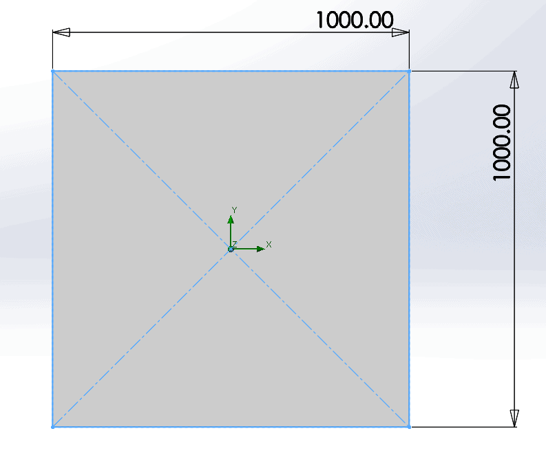
For my example, I made a simple plate with a surface area of 1 square meter (1000mm x 1000mm).
From there the SOLIDWORKS Flow Simulation Setup is easy. Using a simple external analysis, with “heat conduction in solids” and “radiation” turned on, I set the default radiative surface as a blackbody and set the environmental temperature at 300 Kelvin. Radiation must be calculated using degrees Kelvin because it is an absolute value. Lastly, I set a surface goal to measure the radiation rate from the 1 square meter surface.
With these values, the leaving radiation rate can be calculated as follows:

Let’s examine the final answer given to us by SOLIDWORKS Flow Simulation.
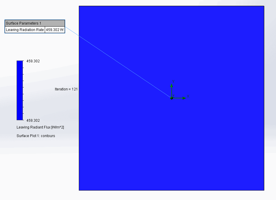
Although the color plot is not very exciting, the value given by SOLIDWORKS Flow Simulation closely correlates to the hand calculation value. 459.3 W from Flow versus 459.29 W calculated by hand. It’s a good exercise to take simple cases like this and correlate simulated values to hand calculations. This gives a high degree of confidence in results from more complex analyses.
I hope this blog has shed some light on the basics of radiation in SOLIDWORKS Flow Simulation. Stay tuned for further blogs on the subject as we will discuss this functionality in more depth.
Matt Sherak
Applications Engineer, Simulation
Computer Aided Technology, LLC