Should You Defeature Parts for SOLIDWORKS Plastics Analysis?
If you design injection molded parts, how often do you include a text feature on one or more faces of the design? What does that text convey to someone looking at the part? In my experience, the included text is likely a part number, a lot number, a product name, or occasionally instructions for use. While I need that level of detail on the finished product, do I really need to include it in SOLIDWORKS Plastics injection molding analysis? I believe those text features should be removed and I will use the remainder of this blog to explain why.
If I plan to perform structural analysis on the design, one of the first steps in planning the finite element model is defeaturing the part. Defeaturing geometry is something most of us are familiar with. The intent is to simplify geometry by removing any features that I do not believe will be relevant for simulation. I like to think about this in terms of load bearing or non-load bearing when preparing for structural analysis. If the feature is small and will not significantly contribute to the structural performance of the design, I remove it from the CAD model before beginning any analysis work. Shouldn’t we do the same for injection molding analysis?
In this simple example, I will start with a SOLIDWORKS CAD model of the Computer Aided Technology logo. With this version, I have suppressed two text features from the model. I then created a SOLIDWORKS Plastics project to perform a Fill analysis on the part using a shell mesh. In the setup, I specified a polypropylene resin and used default conditions for melt temperature, mold temperature, and injection pressure. The injection location is a vertex towards one of the ‘corners’ of the logo, the red cone shaped feature seen in Figure 1.
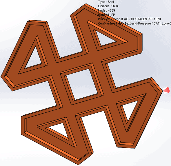
Figure 1.
The pertinent details of this analysis are solution time, mesh size, and the output quantity “pressure at end of fill”. On my Dell Precision 7760 mobile workstation, the solve time was 48.6 seconds to perform the fill analysis. The default sized, curvature-based mesh has approximately 9,700 elements and 4,800 nodes. The maximum injection pressure for the analysis was 5.12 Megapascal. The mesh details and injection pressure results are shown in Figure 2.
Figure 2.
What if instead of defeaturing the part of small text features, I left them in the model for a SOLIDWORKS Plastics Fill analysis? The non-defeatured part is shown in Figure 3. Yes, the blurring is intentional, or I will give away the answer too soon!

Figure 3.
Using the same setup and boundary conditions for the defeatured CAD model, I first tried to create a curvature-based mesh with the default mesh size. The small text features will, of course, increase the mesh size but the resolution of the text, in my opinion, is poor (Figure 4).
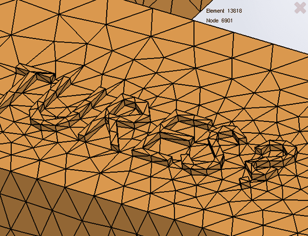
Figure 4.
To improve the quality of the text on the part, I added mesh control of 0.75mm to the top face of every letter of the text features. The text features protrude 0.5mm from the main surface of the part – I could have used an even smaller mesh control size for better text resolution! As you can already see in the upper, right corner of Figure 5, the mesh details are now approximately 23,600 nodes and 11,800 elements.
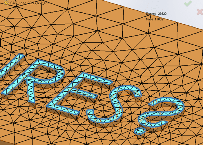
Figure 5.
SOLIDWORKS Plastics analysis, like any other computer simulation, will take longer to solve if the size of the problem is increased. How much longer? For this simple model, the solve time for the fill analysis was 184.6 seconds, a 3.8x increase! The maximum injection pressure also increased to 10.66 Megapascal (Figure 6).
Figure 6.
The increased solution time makes sense, but a larger problem size does not explain why the injection pressure increased by a factor of 2.1. To understand why the maximum injection pressure increased requires a peek under the hood, so to speak, of the SOLIDWORKS Plastics solver. I could just state that the reason is a big mathematical problem, and that would be completely correct.
In my example problem, the SOLIDWORKS Plastics solver will continue to increase the injection pressure until the plastic melt front fills the complete volume, meaning the molten resin has contacted all faces of the part cavity. The math problem is not complete until 100% of the part surfaces, including all the text, has 100% filled. In a real-world injection molding process, the text will only partially be filled. We can see and (most of the time) easily read the molded-in text on a part because the root of the text has well defined edges. The top surface of the text would look much like a SOLIDWORKS CAD dome feature, if you are familiar with that. While there will be a slight increase in maximum injection pressure for the real-world injection molding process, it will not be double the value calculated in the text defeatured example.
Back to what I originally posed at the beginning of this blog, should I defeature plastic part designs for injection molding analysis? In this simple example, injection pressure and solve time were negatively impacted when I solved a Fill analysis on the non-defeatured part. Personally, I recommend spending a few minutes to create a defeatured configuration of your part file(s) prior to beginning any analysis. In preparing for a SOLIDWORKS Plastics analysis, defeaturing always includes removing text features from the design. I want to get answers as quickly and efficiently as possible. A little bit of CAD preparation prior to analysis goes a long way towards making this happen. Now go make your products better with SOLIDWORKS Simulation!
Bill Reuss
Product Specialist, Simulation
Computer Aided Technology