SOLIDWORKS: Simulation On Thin Objects and Non-Circular Springs
Simulation On Thin Objects and Non-Circular Springs
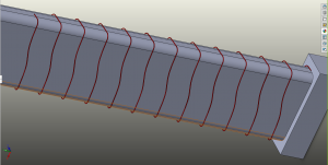
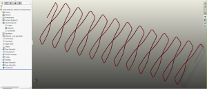
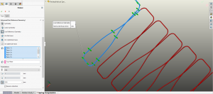
Often times we need to be able to know the stresses on thin members such as springs and clips. Making these objects in SOLIDWORKS can be an adventure, but more often than not, simulating them can be just a plain headache. Circular springs are easier to simulate because all of the loading is axial and the spring profile is circular. For this reason, I chose a non-circular spring. Here is an example of a non-circular spring from a piece of machinery that is being compressed 200 mm:
First, just a quick lesson on how it was made. First, a rectangular boss extrude was made with a helix through the middle of it. Then the corners were filleted.
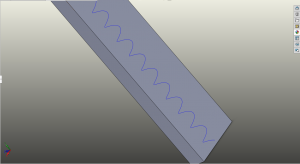
Using the helix as a guide curve and a straight line drawn out from the end of the helix, a swept surface can make the shape below:
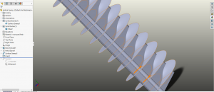
Using the Intersection Curve tool SOLIDWORKS was able to get a nice 3d sketch of the intersection profile and use that for a circular profile sweep.
Now that the spring is made, all that is left to do is an analysis on it. As per most analyses, it is best to make sure it is simulated in a way that is most like its real world conditions. So first, apply a realistic material to it using the Plain Carbon Steel from the SOLIDWORKS Material Library. Most springs are made from carbon steels or stainless so this is a decent choice.
Next, apply some fixtures to restrain the model correctly and eliminate any rigid body motion. Keep in mind that the best way to do this is to restrain it as close to real life conditions as possible. The whole model could be meshed with the guide post and backing plate, but that would create elements that are out of the scope of this study and take extra computational resources (and time). Therefore, SOLIDWORKS Simulation Advanced Fixtures will be used.
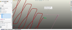
First, the bottom-most part of the spring will be restrained. As per the picture below, the end face of the spring is selected and is kept from moving in the normal direction from the top plane by specifying zero in the box.
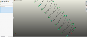
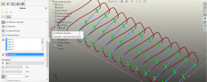
Next, the two sides of the model will be restrained from moving in any direction but the “Y” direction (the direction the compression will be in). So the wider side of the spring will be restrained similarly as the one above by using Advanced Fixtures and selecting all of the faces on that side of the model and specifying zero in the Normal to Plane box. The same is done with the narrower side of the spring. See pictures below:
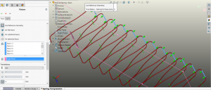
The above restraints will effectively simulate the shaft and the stop at the bottom that physically restrain the spring. Now the load will be applied as a displacement at the top of the spring. This is done in a nearly identical way as the restraints we created. Selecting the top faces of the spring (the first revolution at the top of the spring) allows the application of a prescribed displacement of 200mm. See below:
Once all restraints and loading are in place, the model can now be meshed to prepare for static analysis. A curvature based mesh will be used with default mesh sizes.
As with any analysis, the assumptions need to be known. To state the assumptions of this analysis:
1) The spring material is linear in nature up to yield stress.
2) The loading is done in a way conducive with static loading (loaded slowly enough).
3) The spring will not be driven past yield point.
4) The spring is much softer than the material it is pushing against.
5) The effects of friction between spring and shaft are negligible.
With the assumptions defined and the mesh created, the model can now be solved.
Results appear below.
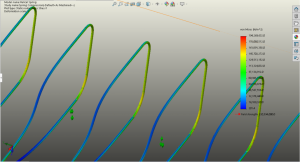
According to the solution given the model does not go over its yield point (Max stress is about 190 MPa and yield is about 220 MPa). Also, most of the stress seems to be concentrated in the corners and the narrower side of the spring. However, upon closer inspection of these areas, it can be seen that the stress colors are “splotchy” and not as uniform as would be expected.
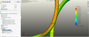
This kind of non-uniformity is a telltale sign of an artificial stress riser, or elements that are just too big. In this case, an artificial stress riser is unlikely in that there are no sharp 90 degree corners, so the elements will need to be made smaller. See the “splotchy” results below:
The global mesh for the model could be set to a finer value, but that would result in many more elements, and therefore a much longer solution time. Instead, a Mesh Control will be added to the corners of the spring (where the stress seems to be highest). Mesh Control is a tool in SOLIDWORKS Simulation that allows the user to locally refine the mesh elements to make them smaller. By right clicking on Mesh in the Simulation Tree, the Mesh Control dialogue can be opened. It looks very similar to the regular meshing screen. For the purpose of this model, I moved the mesh slider all the way to the right indicating a fine mesh on these corners. This does increase the number of elements in the model but not as much as a global mesh refinement would have. After re-meshing and then running the study again, the results of the area in question can be seen below:
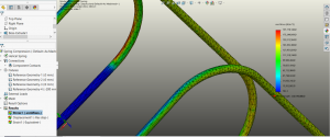
The corner in the background was left at default mesh size for comparison. It can be seen that the stress concentration on the closer corner is much more uniform that the one in the background.
Mesh controls are an integral part of Finite Element Analysis in SOLIDWORKS Simulation. Thin members such as springs and sheet metal parts benefit particularly well from applying mesh controls around corners and bends. For more about mesh controls and thin part analysis please refer to the SOLIDWORKS tutorials or your local CATI/MCAD SOLIDWORKS Simulation training schedule.
Matt Sherak
Application Engineer
Computer Aided Technology