SOLIDWORKS SIMULATION TECH TIP: Transferring Flow Loads to Shell Elements
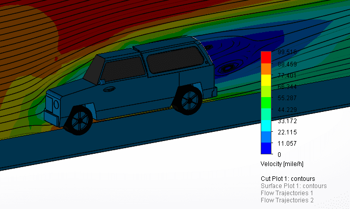
In this example, there is 90mph airflow over the truck body. To start this problem, I ran through the Flow Simulation Wizard tool and set the problem as an external flow analysis. I gave the moving fluid (air) an initial velocity of 90 mph normal to the truck body and ran the study. If I want to see how aerodynamic my model is, I can view flow trajectories over my model. Figure 1 shows a cut plot of the velocities over the body with flow trajectories modeled as streamlines.
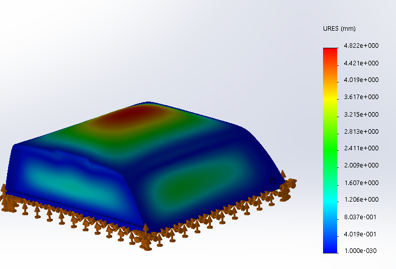
Like this example, one main application where the combination of these tools is handy is flow over a body to identify lift. Lift is a force that acts on the body perpendicular to the direction of the airflow and is in contrast with drag. In this example, I was able to successfully run a fluid simulation over the truck and import those pressure gradients into Finite Element Analysis. The FEA gave me the displacements of the model as a function of the lift force on the model, as shown in Figure 2.
Being able to work with a diverse toolset in SOLIDWORKS gives me the ability to analyze multiple conditions in one single interface. If my model isn’t as aerodynamic or as stiff as it needs to be, I have the ability in SOLIDWORKS to run analytical studies concurrent to my design process. If I were to use a third party program, I would be constantly importing and exporting between the software packages to ensure an optimum design. In SOLIDWORKS, I can do all of this in one easy interface.
For more training and tutorials on the many 3D CAD Modeling solutions in the SolidWorks family of products and add-ons, register for an upcoming Event or look into our SOLIDWORKS training.
Related Articles