SOLIDWORKS Flow Simulation: HVAC Module Part 1 - Tracer Study
Predicting the way that fluids behave and mix inside a closed space can be a difficult undertaking. Every day we are at the mercy of the HVAC systems that not only expel or filter harmful air but maintain comfortable temperatures. There is a lot to consider in these types of problems, and without some sort of assistance, it can be little more than guesswork. SOLIDWORKS Flow Simulation does a great job of calculating the types of parameters we are used to in office and industrial environments. To gain even more fidelity, SOLIDWORKS Flow Simulation’s HVAC module has some tools that are specifically designed to help the HVAC industry solve these types of problems. Today we are going to talk about one of the HVAC module’s flagship capabilities, the Tracer Study.
Those who have used SOLIDWORKS Flow Simulation in the past may be familiar with particle studies. These are used to inject small bits of matter into a fluid to see where they end up according to the flow field. A tracer study works in a similar fashion, except a tracer study injects a small admixture of other fluids into the domain. The assumption is that it is a small enough amount of the mixture to not change the global domain’s flow field. Both study types are secondary calculations done AFTER the main solver has completed.
Let’s look at an example. Below you can see an exhaust hood. These are common in laboratories and are used to conduct chemical reactions in a way that the fumes will not be inhaled by the operator. There is a big open face at the front that represents the environment we must keep safe, and a face at the back that represents an outlet airflow that should pull the gas away from the hood opening.
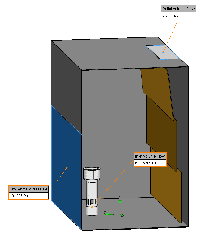
We will be using a carbon monoxide (CO) mixture as the tracer. This is a deadly gas in high concentrations and should be kept away from any person in the lab.
To start a tracer study, it is easiest to use the wizard.
The tracer study will ask you to specify the type of tracer (CO in our case), any initial distribution it may have, its sources, and optional wall conditions to calculate condensate on faces of the model. See steps in the order they appear below:
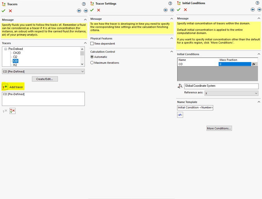
The astute reader might have noticed some of the advanced capabilities shown in those screenshots. The tracer study allows the user to define not just one, but as many simultaneous admixtures as they would like. Tracer Study also has the ability to be time-dependent, solved in a transient study, not just steady state. You can even define a local area to have an initially high level of whatever admixture you would like.
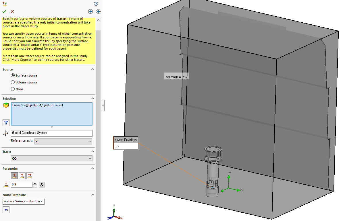
For our tracer, we simply set up a surface source in the center of the ejector in the exhaust hood. The source constitutes a 0.9 mass fraction of CO from that surface. As judicious engineers, we must make sure that the CO does not reach dangerous levels around the user’s opening. So, after solving the Flow Project to calculate the flow field and then running the tracer study we can look at the results.
The tracer study allows for extra parameters for post-processing the first of which is the “Tracer Mass Fraction.” See below:
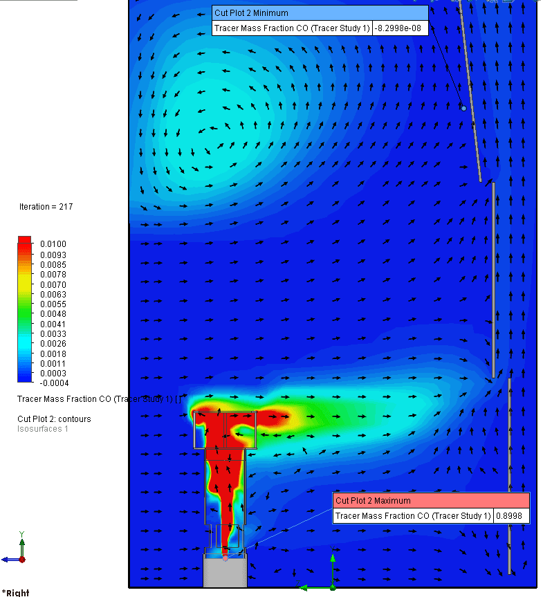
As you can see, the CO is dissipated quickly from the ejector. A 0.01 mass fraction is still far more than is acceptable, but the plot shows most of the air moving away from the opening, and just a little bit getting stuck and re-circulated towards the top left. We can verify this further with an Isosurface plot.
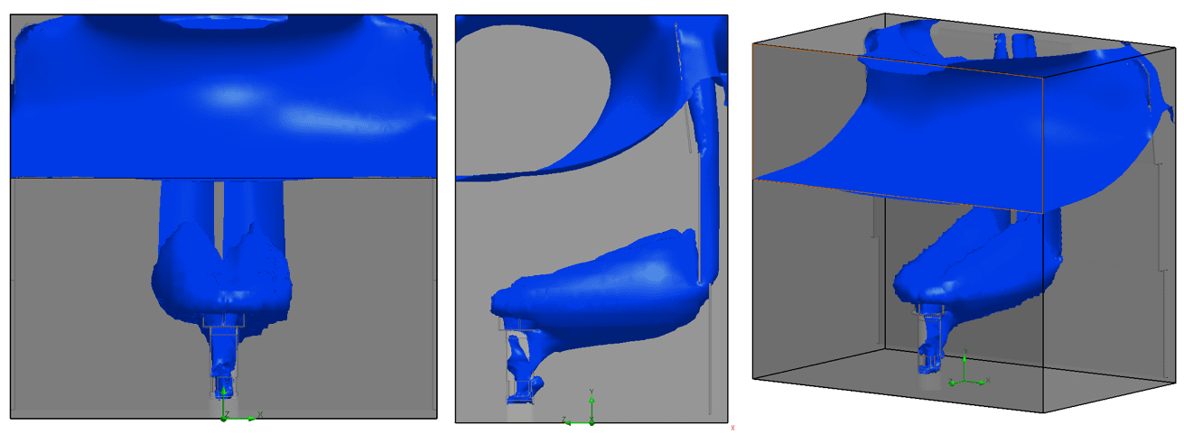
This isosurface is set at a mass fraction of 0.0001875 which according to an online calculator amounts to about 150 ppm (parts per million) of CO. This concentration of Carbon Monoxide can be deadly in 10-50 minutes according to some sources. The isosurface shows that deadly concentration of CO is dangerously close reaching the outside world. Most of it is either being pulled out by the exhaust fan or held in the upper part of the hood. To know for sure, we will do a few surface plots.
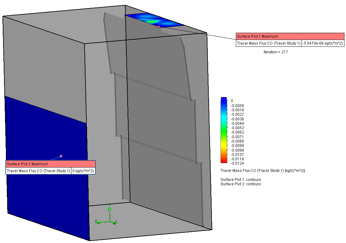
The surface plot verifies that there is indeed zero CO coming out of the front of the exhaust hood assembly. The plot maximum for the opening shows zero mass flux of CO on that surface.
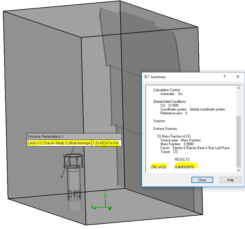
Mass fraction, flux and flow rate of the admixture are not the only outputs granted by a tracer study either. Other HVAC industry parameters that indicate the effectiveness of the system are calculated as well. The LAQI (Local Air Quality Index) index is calculated along with the CRE (Contaminant Removal Effectiveness) index. The LAQI measures the effectiveness of a system for removing contaminated air from a point. For a perfect mixing system, LAQI is 1. Anything above one indicates a better capacity for contaminant removal. The CRE is similar. A CRE of 1 is a perfect mixing system. Values below 1 are poor and values above 1 are considered good.
SOLIDWORKS Flow Simulation’s HVAC Module is a powerhouse when it comes to having the utmost confidence in the safety, comfort, and performance of a building’s HVAC system. Tracer study is only one of the many capabilities added by this module. Stay tuned for future blogs on the HVAC module of SOLIDWORKS Flow Simulation. Until then, keep innovating!
Matt Sherak
Applications Engineer, Simulation
Computer Aided Technology, LLC