SOLIDWORKS Motion Joint Forces
Simulation tools are meant to recreate reality but sometimes this is easier said than done! If you don’t accurately capture real world behavior in your setup, you will likely miss an important part of the solution or get results that are highly inaccurate. This can be the case for SOLIDWORKS Motion joint forces.
In construction industry excavators, dual hydraulic actuators are sometimes used to support high loads and distribute them through the main structure, as for the main boom shown below. Worst-case loading on these actuators is encountered when lifting a full bucket of heavy material such as soil or rocks. Sizing of the actuators and the design of their connection to the rest of the machine require accurate knowledge of the maximum forces they will support during the operation cycle. We can use SOLIDWORKS Motion to generate a load curve for the bucket lift operation through the full range of motion.
After building the assembly using the appropriate mates to correctly represent the action of all the joints, and switching to the Motion manager tab, Motion will automatically map the mates to the study. Then all that is needed is to define the loads on the structure and the driving motors. (Please see the Motion tutorials accessible from the SOLIDWORKS Help pulldown menu if you aren’t familiar with the setup and results generation.)
Examining the mates in the excavator, we see that concentric mates 18 and 21 are used to position each of the main boom actuators. This makes sense from an assembly buildup standpoint; each component must be properly located within the assembly.
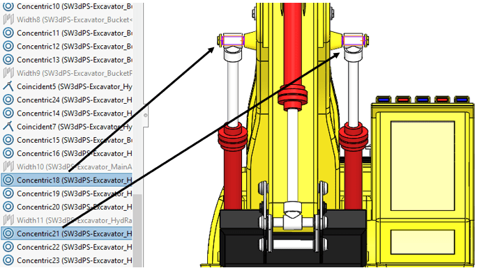
The kinematic solution gives us forces at each mate location. Extracting the reaction forces at these two locations with a time-history plot, we see that the results don’t make sense. One actuator joint has zero force!
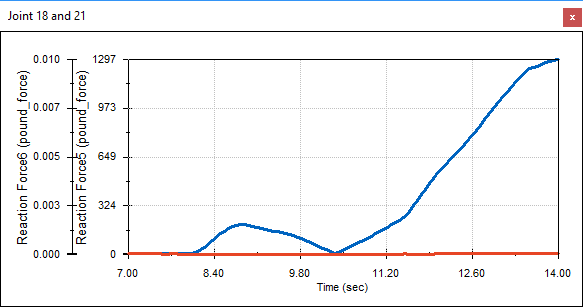
This is where the disconnect between reality and simulation comes in and needs to be accounted for. The solution we’ve obtained assumes rigid parts, whereas there will be some deformation and load distribution between the two actuators in the real machine. For the simulation, we refer to this as a redundancy in the system. Mathematically, one of the redundancies is automatically eliminated, thus the zero force on one of the actuators. An easy solution is to simply divide the result for the nonzero actuator by two (1297 lbf / 2). Each one will support a maximum of approximately 650 lbf.
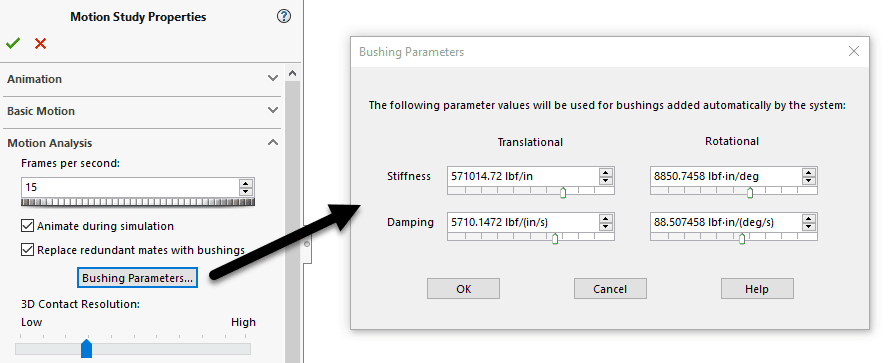
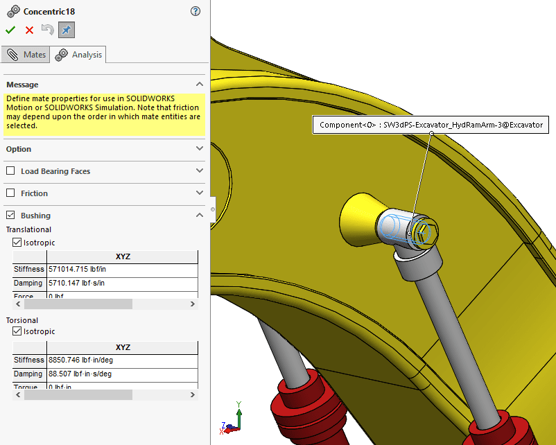
Another way to account for the rigid assumption in Motion and allow for a distribution of the load between the two actuators, is to add flexible bushings to the joints. This can be done using the same stiffness value for all the joints through the Motion Study Properties,
…or at each individual mate within the Analysis tab of the mate property manager.
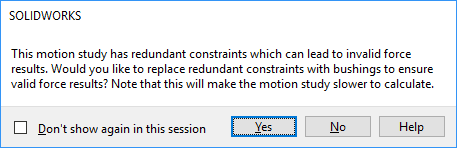
Don’t worry, when you create a plot of joint reaction forces, the program will warn you about the redundancies and allow you to replace the joints with bushings.
So, when you are faced with a Motion simulation that requires extracting accurate joint forces, remember that you are working with rigid assembly components, but the bushing functionality can be used to introduce the necessary flexibility.
Kurt Kurtin
Manager, Simulation and Electrical Products
Computer Aided Technology, LLC