SOLIDWORKS Plastics: Shell Mesh vs Solid Mesh
SOLIDWORKS Plastics: Shell Mesh vs Solid Mesh
SOLIDWORKS Plastics is an injection molding add-in to SOLIDWORKS. Plastics comes in 3 levels, Standard, Professional, and Premium that are geared towards plastic part designers, mold designers, and analysts, respectively
Some may say the most crucial part of any simulation is the mesh, and I would be keen to agree. SOLIDWORKS Plastics offers an automatic Solid and Shell meshing algorithm, in addition to more robust manual controls.
When an automatic solid method is selected, the software will select the default size of solid elements based on the cavity size and thickness. The automatic mesh is composed of hexahedral or “brick” elements but will initially render with tetrahedral elements. See below:
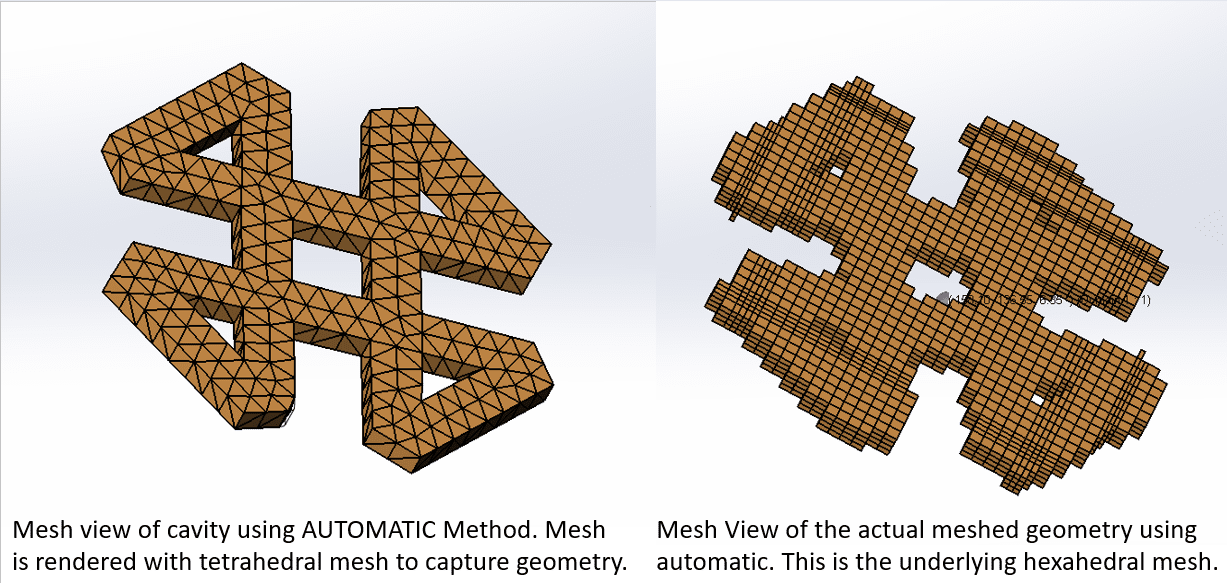
Using the manual mesh technique, the user has much more control over the mesh and more options. As the picture above shows, the automatic mesh is very rudimentary and not great for an in-depth analysis.
The shell mesh option allows the program to mesh just the outside surfaces of a part. This mesh is recommended for parts with a uniform thickness. A shell mesh looks like the picture above, on the left. However, using a shell mesh alone will not yield a great flow filed calculation, as there is no mesh in the center of the part.
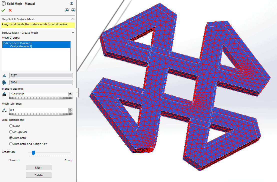
I most cases, a dense manual SOLID mesh is preferred. Once in the SOLID mesh dialogue, the program will prompt for what domains are to be meshed, then what type of domain each of them are (mold, cavity, runner, etc.) Once the domains are properly defined, the next step is to create the surface mesh. If a previous surface mesh was created, that can be used here, or a new one can be created. Notice here that the user has a lot of potions to control mesh size, refinement, tolerances, etc.
Once the shell mesh is created, the program gives some great feedback on the mesh and then a screen that allows the user full control to fix any errors that may have arisen.
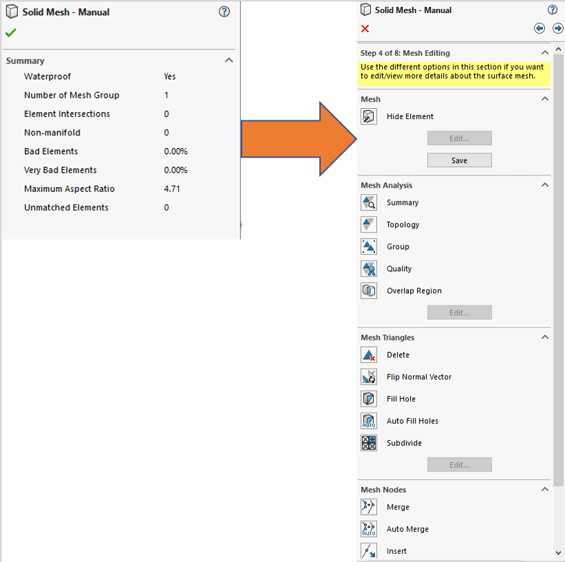
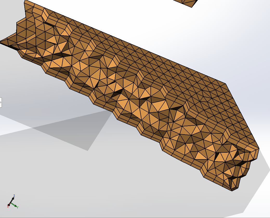
Finally, we get to begin creating the Solid mesh. There is an option for Hexahedral (brick) or tetrahedral (triangular) mesh types. As we saw above, the hexahedral mesh is struggling to capture this geometry, so for this example a tetrahedral mesh will be created.
In most cases, the Hybrid tetrahedral mesh gives the best results for Cavities, inserts and runners. This type of mesh creates prism (or “wedge”) elements on the surface mesh and transitions them into tetrahedral elements in the core of the part.
Once the mesh is created, add the other boundary conditions that are needed for the type of analysis, and run the study! SOLIDWORKS has recommendations on the Plastics Help site for which type of SOLID mesh to run for certain analyses, see screenshot and link below. I recommend looking there for more specifics regarding meshing.
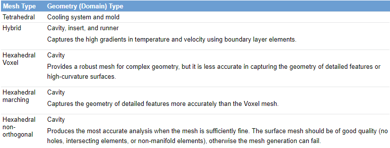 (Credit DS SOLIDWORKS)
http://help.solidworks.com/2018/English/swplastics/c_SOLIDWORKS_Plastics_Welcome.htm
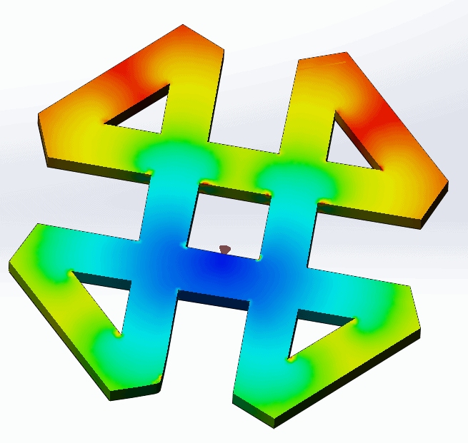
]Thank you for taking the time to read about meshing in SOLIDWORKS Plastics, it is an essential tool for anyone who has involvement in injection molding. Finally, just because SOLIDWORKS Plastics is best talked about with some color, here is a picture of the solved study!
Thank you,
Matt Sherak
Applications Engineer, Simulation