SOLIDWORKS Plastics Venting Analysis
Recently, I was helping one of our customers work through a large injection molding analysis using SOLIDWORKS Plastics. He wanted to verify weld lines and air traps as he was still planning gate and vent locations on the tooling. The part he was analyzing included many features, such as mounting bosses and stiffening ribs, on the inside. These features will all be on the core of the mold. The exterior of the part will have a near-smooth finish, an “appearance” part. The cavity of the injection mold tool will be polished to create the high-quality surface that is desired. I’m going to focus on two of the decisions – gate location and venting – on a representative part.
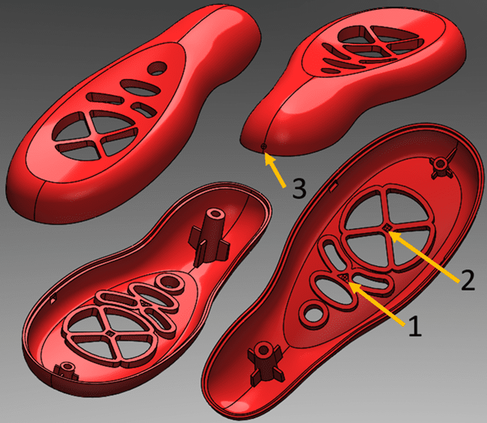
The first decision is where to gate the part. Ideally, you would like to place the gate near the center of mass (which you can find using Mass Properties in SOLIDWORKS), so the part cavity fills evenly. In my example, location 1 is very close to the part center of mass, a small triangular indentation on the inside of the part. A second gate location could be at 2, where plastic would flow outwards from the X-feature. Both locations present interesting challenges, one of which would be the need to both inject and eject from the cavity of the injection mold tool. These internal features should be on the core side of the tooling, so this choice would require flipping the part orientation in the mold design. While this is possible, it could be quite an expensive tooling choice. (Honestly, I had to verify that an inject-eject system on the cavity was possible, so I called a good friend, Blaine, who designs injection mold tooling!) Choosing similar regions on the outside of the part would put the gate in highly visible locations, which is less than ideal. The compromise is to choose a gate on the ‘appearance’ side of the part near the end, location 3.
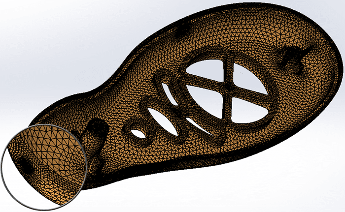
Now that a gate location has been selected, the process for analyzing the part with SOLIDWORKS Plastics can begin. I will create a shell mesh, a 2D representation that skins the part. I will include mesh refinement in areas of interest and verify the complete mesh is sufficiently refined over the entire part for this first-pass analysis. Here you can see the refinement at the gate location, the small bosses and ribs, around the mating surfaces for internal buttons and electronics, near the undercuts, and around the thin rim of the part at the appearance gap.
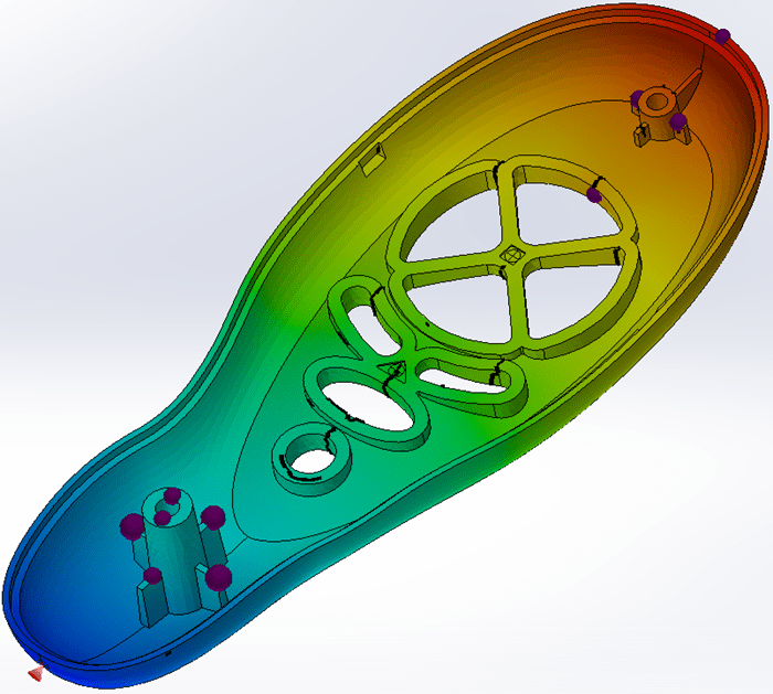
To finish setting up this initial SOLIDWORKS Plastics project, I need to assign a material, verify/modify the FILL settings, and choose a gate location for the analysis. Once these steps are complete, I solve the SOLIDWORKS Plastics FLOW analysis and review the first-pass results. With this preliminary work I am most interested in injection pressure, mold clamping forces, predicted weld line locations and predicted air trap locations. In this picture, I’ve overlaid the weld lines (black lines) and air traps (purple spheres) on the SOLIDWORKS Plastics Fill Time result plot.
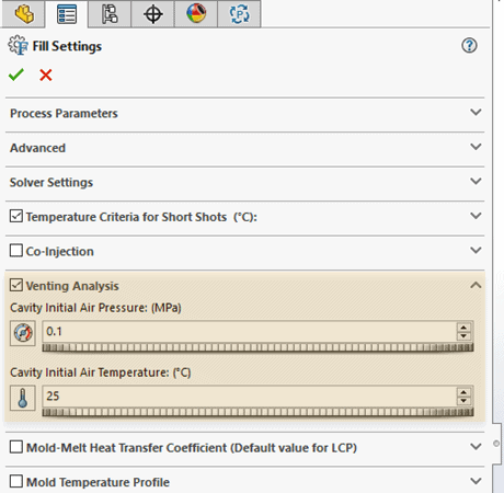
With my first-pass analysis complete, I’m ready to work on a more complex analysis with a solid, 3D mesh. I will duplicate this SOLIDWORKS Plastics study and create a 3D mesh, reusing the 2D shell mesh data as the starting point. After transforming the 2D mesh into a 3D mesh, I’ll use the same material, gate location, and FILL settings. The FILL settings will, however, have one addition. I need to turn on the option for Venting Analysis. Venting Analysis is only possible with a 3D mesh and requires SOLIDWORKS Plastics Professional or SOLIDWORKS Plastics Premium. When I turn on this option, I need to verify the cavity initial air temperature and pressure. Note that the default for initial air pressure in the cavity is 0.1 MPa (absolute pressure, not gauge pressure), which is slightly less than atmospheric pressure.
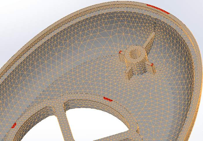
Also, I need to add where vents will be located by utilizing the ‘Air Vents’ option under Boundary Conditions for this SOLIDWORKS Plastics study. The air vents are added to the study by using your computer mouse to select locations on the mesh, such as the mold parting line or possibly at a planned location for an ejector pin. The vent locations for my analysis are shown in red on the surface of the mesh. I’ll use the air trap locations identified in the 2D shell mesh study as guidance.
Once these setup steps are complete, I will solve this 3D mesh study with the venting option and review the SOLIDWORKS Plastics results. Like the shell mesh study, many of the post-processing options are the same. I can still view the fill of plastic into the part, review estimates for cooling time, sink marks, injection pressures, and much more. But there is one additional quantity that I’m most interested in – Venting Pressure! Without sufficient venting in the injection mold tooling, air inside the cavity will compress as the hot, molten plastic fills the cavity. This can cause a defect, known as dieseling, where the trapped air combusts leaving small burn marks on the surface of the part.
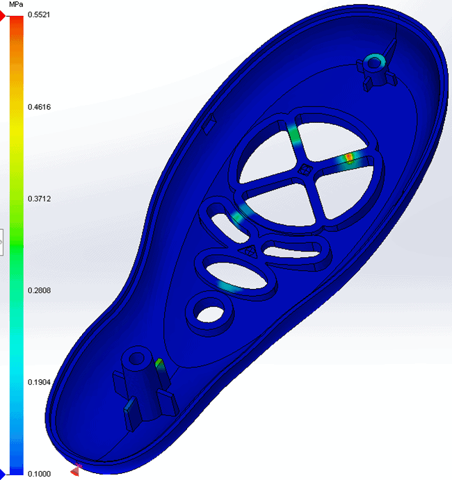
When I view this result plot, I’m looking at the air pressure inside the cavity during the plastic injection phase of the molding process. There will be a few regions inside the cavity where the pressure is higher than the initial condition, 0.1 MPa. In the result plot, I have six different regions that appear. This is where I look for two things – what is the magnitude of the venting pressure and are these near where I assigned air vents. If the highest pressure is less than 1 MPa (145 psi), the mold is adequately vented. If there are regions above 1 MPa venting pressure, I need to assign more air vent locations to the mesh and re-solve the analysis. For this analysis, the maximum venting pressure is 0.55 MPa, so I have sufficient venting with this design.
If I didn’t have the guidance of an Injection Mold Tooling Engineer, I could have utilized SOLIDWORKS Plastics to analyze several different gate locations. Fortunately, a short discussion with Blaine helped to rationalize why injection location 3 made the most sense. That allowed me to focus my SOLIDWORKS Plastics analysis work on the next important decision for the tooling design, the air vent locations in the injection mold tool. Using SOLIDWORKS Plastics, I was able to determine where to add air vents to the mold and verify that the injection mold tool had sufficient venting. How much more effective could you be designing injection mold tools with guidance from SOLIDWORKS Plastics? Now go make your products better with SOLIDWORKS Simulation!

Bill Reuss
Product Specialist, Simulation
Computer Aided Technology, LLC