SOLIDWORKS Simulation: Hand Calculations
Recently, I was discussing the use of hand calculations in conjunction with Finite Element Analysis (FEA) with one of our customers. His belief is that hand calculations are a waste of time, that they are never accurate enough to represent what he designs. Simply put, how can an equation referencing material properties, geometric characteristics, or section properties needed in many structural analysis calculations represent the complex designs he creates today. That is a strong and fair argument that I cannot win in mere minutes. Good thing I’m thinking about the long game here!
While I don’t believe hand calculations are a waste of time, it’s hard to argue against accuracy. My initial response ignores accuracy but focuses on the magnitude of hand calculation results. Admittedly I do have to make assumptions for hand calculations to be valid, but it is within those assumptions that I may have an in to soften his stance. Now, I cannot discuss the exact product design, but in general terms the product must support large loads and can be stacked several products high. I need two different hand calculations for this, one for stress and one for buckling.
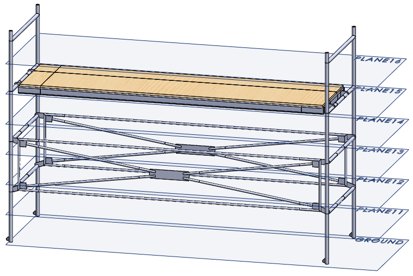
That hand calculation for stress is easy – force divided by area. Estimating the load bearing area for this product is quite challenging. A visual example of the load bearing area could be a scaffolding. The load bearing area through any one cross-section parallel to the ground can be easily found using SOLIDWORKS. I would create several reference planes in the CAD model at a consistent spacing, then measure how much material is at each cross-section, and tabulate the results of those measurements.
There are multiple approaches to a hand calculation for stress at this point of my investigation. I can choose to estimate the stress at each cross section since the maximum load (force) is known. I could also choose to calculate an average of the load bearing areas for all the cross sections to estimate stress through the entire structure. Or I could estimate the maximum expected stress using the smallest area measured.
Let’s assume that I decide to take the smallest cross-sectional area and represent that as a simple shape, like a hollow tube. Yes, this is significantly smaller than the actual product, but it will make sense when I get into the Buckling calculations. I also must assume that the loading conditions act along the axis of the tube as a pure compression load. This is not representative of a stacked product but quantifying the off-axis loading is beyond trying to get a basic understanding of the stress range the product might experience.
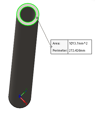
My next assumption is that the loading occurs in multiples of the products stacked height. For simplicity, I will assume that the multiples of the load are per 10,000 N force. My hand calculation for stress, given the assumptions I’ve made, is this:
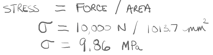
This is a good start, in my opinion. I’ll reference this as 9.86 MPa per “unit load” of the product.
The next hand calculation I need is an estimate the critical load that would cause the product to buckle. This is important because the product is subjected to compression loading. Now I truly must understand the assumptions I’m making for my buckling hand calculation to be “valid”. I’m going to assume the product will buckle like a simple, pinned beam. Is that realistic? Not at all. But if I make that assumption, the critical load can be calculated by this formula:
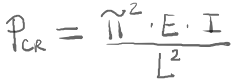
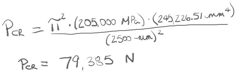
The actual product is an assembly with a few different materials used in the primary structure. I’ll select one material to use here for a value of E, or Young’s Modulus. I will assume that the entire structure is made with AISI 1020 Steel, which has an Elastic Modulus of 205,000 MPa. The length of the beam, L, is the overall height of the product, approximately 2.5 meters. I also need to attempt to estimate the second moment of inertia, I. This is neither simple or accurate for a complex product design!
The key with estimating the second moment of inertia is to get back to the scaffolding example. I’ll go back to the cross-sections used for measuring area and use the overall shape and size of that cross-section to calculate a value for I. This step is a bit time consuming, so I may only do this for a small subset of the area cross-sections. I could also use the Section Properties tool in SOLIDWORKS for each section plane, which may save a little time. Going back to my simplification of the product being a hollow tube, I would need a single value for I. Keeping with the use of the minimum cross-sectional area for calculating stress, I will use the one cross-section that had the minimum second moment of inertia of all the cross-sections measured. Using the same hollow tube to represent the complex product, the Section Properties measurement in SOLIDWORKS shows the I-value needed for the hand calculation.
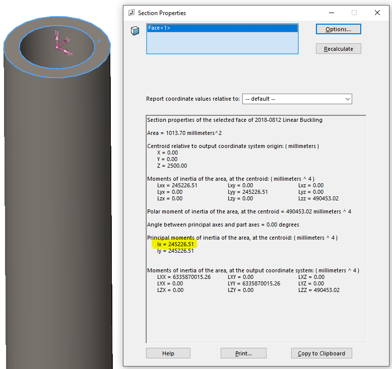
If the product shape were idealized as something other than a hollow tube, the values for Ix and Iy in the Section Properties dialog would be different. In that case, I would use the lower of the two values for the hand calculation. Now I have all the inputs I need to estimate Linear Buckling. The hand calculation is:
As a quick check of the critical buckling load, I can solve this in SOLIDWORKS Simulation. The hollow tube is modeled as a weldment, so the body will be meshed with 1D Beam elements. At the bottom beam joint, I need to set up a reference geometry restraint to represent a simple pinned beam.
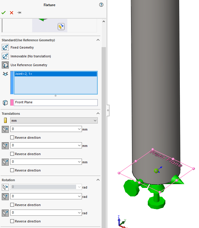
I’ll restrict all three translations along X, Y, and Z, and restrict the rotations about Y and Z. This leaves the rotation about X to represent the pin. At the top, load bearing end of the beam I have a similar restraint set up. The one exception is I need to leave the axial translation free, not restricting the beam from compressing along the Z-axis. The force I will use for the buckling analysis is 1 N. When I solve this in SOLIDWORKS Simulation Professional, the Buckling Load Factor is equivalent to the critical load, which is 77,303 N.
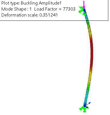
The FEA solution to Linear Buckling is 2.6% less than my hand calculation, but this provides a quick verification of my hand calculations. Going back to my hand calculations for stress, these two buckling results estimate that the product should be able to withstand approximately eight “unit loads” of the 10,000 N force before buckling would occur.
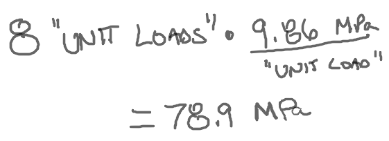
This indicates that the maximum stress in the product on the bottom of the stack would be nearly 80 MPa when eight units are stacked on top of one another. The yield strength of AISI 1020 steel is 350 MPa, more than 4.4x greater than the critical buckling load. Now I’ve made a lot of assumptions to get to this point, but even with all of those understood I can be reasonably confident in saying the product will buckle before it will yield.
How accurate are my hand calculations? I don’t believe I can quantify that at all given the number of assumptions made to come up with a few numbers. So why did I go through the hand calculations? Quite simply it was for the magnitude of the hand calculation results. Eventually, the product will be analyzed with SOLIDWORKS Simulation. When it is, I would not expect the results to be an order of magnitude higher. If they are, I fully expect to hear about it! So the next time you’re getting ready to analyze a big, complex model you should start with some assumptions and hand calculations to help in both your thinking and understanding of the product. Then use SOLIDWORKS Simulation to confirm what you did by hand. Now go make your products better with SOLIDWORKS Simulation!

Bill Reuss
Product Specialist, Simulation
Computer Aided Technology, Inc