SOLIDWORKS Simulation Premium: An Overview of Dynamic Damping
In this blog, I will provide an overview of dynamic damping, show examples of a system under various levels of damping, and give some insight on how to define damping in a SOLIDWORKS Dynamic simulation. For those seeking a deep dive into damping, this is not that blog article.
What is Damping:
According to Isaac Newton, “…an object in motion stays in motion with the same speed and in the same direction unless acted upon by an unbalanced force.” This “unbalanced force” that Newton mentions includes forces like friction, air resistance, etc. Looking specifically at an oscillating system, we refer to these unbalanced forces as damping. To further understand, let’s look at how Oxford defines damping; “A reduction in the amplitude of an oscillation as a result of energy being drained from the system to overcome frictional or other resistive forces.”
Although not required, we recommend that users define damping for more realistic results (see graphs below). Why is damping not defined in a SOLIDWORKS static study? Damping opposes movement in a system and as such requires a dynamic study.
Damping Levels:
A system can be damped at various levels. These levels are: undamped, under-damped, critically damped, and over-damped. Damping is commonly referred to as a ratio between 0 and 1. 1 represents critical damping and 0 undamped.
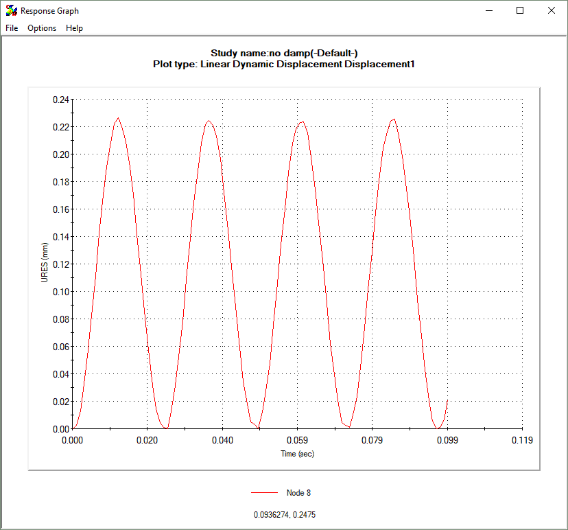
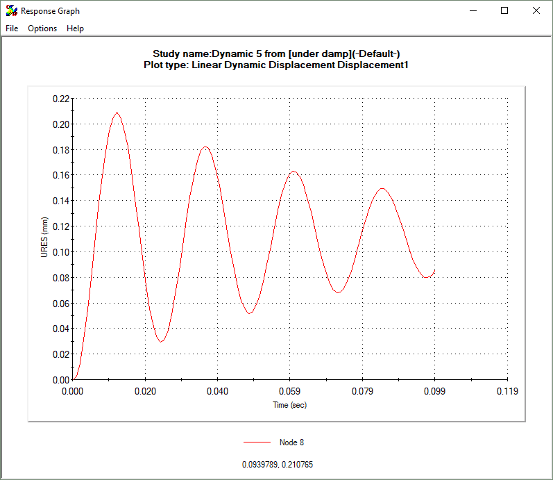
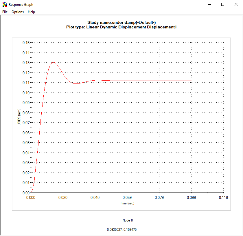
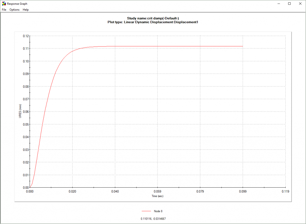
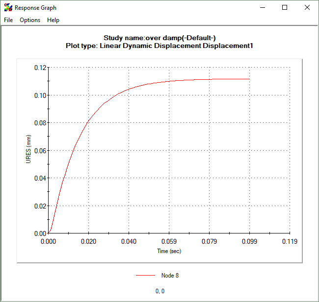
Please refer to the images below to see the effect that these damping levels have on an oscillating system. The vertical axis represents displacement and the horizontal time.
UNDAMPED SYSTEM WITH OSCILLATING LOAD (RATIO = 0)
UNDER-DAMPED SYSTEM WITH OSCILLATING LOAD (RATIO 0.05)
UNDER-DAMPED SYSTEM WITH OSCILLATING LOAD (RATIO 0.5)
CRITICALLY DAMPED SYSTEM WITH OSCILLATING LOAD (RATIO = 1)
OVER-DAMPED SYSTEM WITH OSCILLATING LOAD (RATIO = 2)
What value of damping should I use?
There are 2 ways we will look to define damping in a SOLIDWORKS Dynamic study; modal damping, and Rayleigh damping.
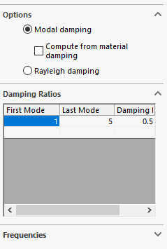
MODAL DAMPING:
For linear dynamic analysis (modal analysis) we can use either of these damping options but for non-linear analysis, we must use Rayleigh damping because for non-linear we do not calculate the resonant modes. In other words, modal damping is only available for modal analysis. For those using linear dynamic analysis, the simplest way to define modal damping is to check the radial button to “Compute from material damping.”
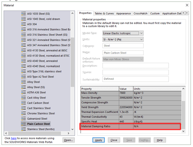
But be aware that the material you use has a Material Damping Ratio defined (this one does not). If a material lacks a damping ratio, you may determine the ratio through experimentation, documentation, or provided by the material manufacturer.
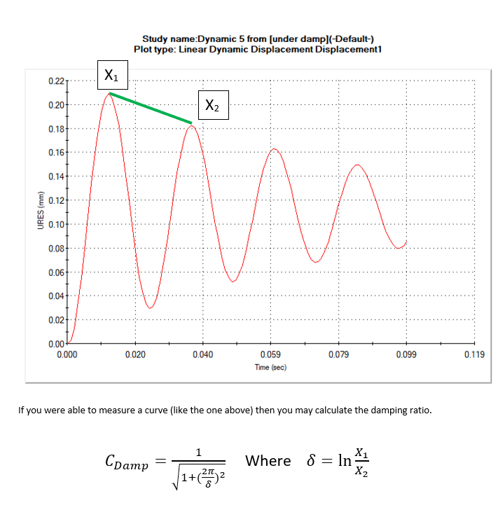
Test it out for yourself! Remember the damping ratio for this graph was 0.05. Take 0.21 as X1 and 0.182 as X2. You should calculate about 0.05 as the damping ratio by using those values in the equation above.
RAYLEIGH DAMPING:
For Rayleigh damping, the inputs required are an alpha and a beta constant. Please refer to this SOLIDWORKS Knowledge Base article for help calculating these constants (you will need to log in to SOLIDWORKS customer portal to view). SOLIDWORKS KB article S-053097
If the link above is not working for you, then log in to the SOLIDWORKS Customer Portal and navigate to the Knowledge Base. Search for S-053097 (the solution number).
Thank you!
Matthew Fetke
Application Engineer
Computer Aided Technology, LLC